E-224-Test Facilities Experiment Review Form
advertisement
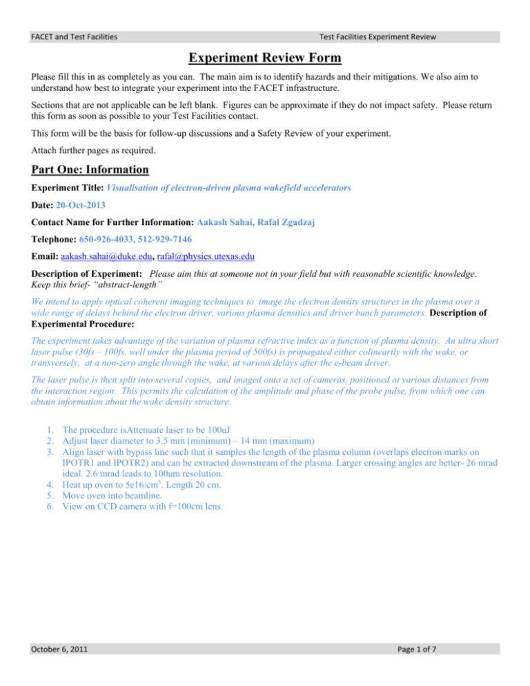
FACET and Test Facilities Test Facilities Experiment Review Experiment Review Form Please fill this in as completely as you can. The main aim is to identify hazards and their mitigations. We also aim to understand how best to integrate your experiment into the FACET infrastructure. Sections that are not applicable can be left blank. Figures can be approximate if they do not impact safety. Please return this form as soon as possible to your Test Facilities contact. This form will be the basis for follow-up discussions and a Safety Review of your experiment. Attach further pages as required. Part One: Information Experiment Title: Visualisation of electron-driven plasma wakefield accelerators Date: 20-Oct-2013 Contact Name for Further Information: Aakash Sahai, Rafal Zgadzaj Telephone: 650-926-4033, 512-929-7146 Email: aakash.sahai@duke.edu, rafal@physics.utexas.edu Description of Experiment: Please aim this at someone not in your field but with reasonable scientific knowledge. Keep this brief- “abstract-length” We intend to apply optical coherent imaging techniques to image the electron density structures in the plasma over a wide range of delays behind the electron driver, various plasma densities and driver bunch parameters. Description of Experimental Procedure: The experiment takes advantage of the variation of plasma refractive index as a function of plasma density. An ultra short laser pulse (30fs – 100fs, well under the plasma period of 500fs) is propagated either colinearily with the wake, or transversely, at a non-zero angle through the wake, at various delays after the e-beam driver. The laser pulse is then split into several copies, and imaged onto a set of cameras, positioned at various distances from the interaction region. This permits the calculation of the amplitude and phase of the probe pulse, from which one can obtain information about the wake density structure. 1. The procedure isAttenuate laser to be 100uJ 2. Adjust laser diameter to 3.5 mm (minimum) – 14 mm (maximum) 3. Align laser with bypass line such that it samples the length of the plasma column (overlaps electron marks on IPOTR1 and IPOTR2) and can be extracted downstream of the plasma. Larger crossing angles are better- 26 mrad ideal. 2.6 mrad leads to 100um resolution. 4. Heat up oven to 5e16/cm3. Length 20 cm. 5. Move oven into beamline. 6. View on CCD camera with f=100cm lens. October 6, 2011 Page 1 of 7 FACET and Test Facilities Test Facilities Experiment Review Part Two: Apparatus You must provide us with drawings and computer models. Dimensions of apparatus: Include any support equipment such as vacuum pumps, electronics, etc. Only minimal new equipment is required. Inside the vacuum chamber - a mirror for coupling the laser pulse in and another for coupling it out. Actuators for these mirrors may be required to satisfy beam clearance pending facilitiy review. Outside of the vacuum chamber - several mirrors and beam splitters, as well as several ccd cameras. 359cm Existing input mirror Output mirror 55cm zzzzzzzzzzzzzzzz M1 75cm plasma Beam tube Laser input Lens f = 100cm CCD Weight: N/A Lead Shielding Requirements: Cameras may require shielding if significant x-ray noise will be present in the images. Description of mechanical controls: Manual actuators on mirrors for angular adjustments of the mirrors. Description of electronic controls: Remote control for cameras and possibly for mirror actuators, if such will be used. Delay control of the time delay between the laser pulses and electron bunches. October 6, 2011 Page 2 of 7 FACET and Test Facilities Test Facilities Experiment Review Cabling requirements: Some cabling will be required for the cameras and possibly the actuators. These would be power cables and computer or network interface cables. Part Three: Computing Description of controls software: Camera control and acquisition software. Possibly actuator control software. It is expected that existing SLAC software will be used. Description of data acquisition systems or computers: Existing SLAC acquisition systems will be used. Networked resources or software you need access to: Access to collected image data and electron beam parameters. October 6, 2011 Page 3 of 7 FACET and Test Facilities Test Facilities Experiment Review Part Four: Radiation List All materials and devices that will be in the accelerator tunnel during beam operation: Several glass mirrors, lenses, mounts for these optics, cameras. List all samples or other materials that are directly in the beam or could feasibly be in the beam from a beam missteer or misalignment of samples. (Include diagnostic screens and devices, sample materials including any supporting substrate, brackets or carriers. State material and length): Probe laser beam input mirror and output mirrors could be shifted into the electron beam due to misalignment. The material would be fused silica or BK7 glass, with a length of about a centimeter for small misalignments. For larger misalignments, the beam could fall on the mounts of the mirrors, which consist mainly of aluminum, with smaller steel and brass coponents, like screws, springs, etc. Please complete the checklist and comment on any “yes” below or on a separate sheet: Yes No Experiment contains: Radiologically active materials that will need to be taken off site (e.g.: samples exposed to the beam) Potentially activated materials will need to be taken off site, including cameras and other instrumentation that has been in the beam tunnel during beam operation. Non-Ionizing Radiation (RF) – State frequency and the maximum possible peak and average power. Do not list radiation from normal instrumentation and logic (e.g.: TTL) sources. Comments: October 6, 2011 Page 4 of 7 FACET and Test Facilities Test Facilities Experiment Review Part Five: Hazard and Mitigation Analysis Please complete the checklist and comment on any “yes” below: Yes No Experiment contains: Hazardous Materials. List any material considered hazardous by the State of California Specialized Chemicals. List any chemicals used in the experiment or support equipment. Include pump oils, vacuum greases used on o-rings, etc. Flammable materials. (Materials that can ignite and burn easily at room temperature.) Compressed Gases Potentially pressurized system (Greater than 15 psig.) Cryogens Nano-scale Materials Biological Materials Radiological sources Equipment has been exposed to a particle beam or may be radiologically activated. Lasers (state class) Comments: Hydrogen gas may be used in the vacuum chamber at low pressure and would be stored in a tank at high pressure. We believe that such storage and delivery system already exists and would not need to be altered. Glass mirrors, aluminum mounts for the mirrors, which also contain steel springs, screws and balls, as well as brass components could become activated by the electron beam if misaligned. Laser pulses required for this experiment would be <1mJ per pulse with durations of ~10’s of femtoseconds. List Electrical Equipment that will need to be EEIP tested on arrival at SLAC: October 6, 2011 Page 5 of 7 FACET and Test Facilities Test Facilities Experiment Review Please complete the following tables (examples are given to help you): Potential Electrical Hazards (e.g.: heater leads, high voltage vacuum feedthroughs) Item Heater Leads Hazard Shock hazard - Heaters operate at 150 Volts Vacuum feedthrough Bias voltage for detector – 100 volts Mitigation Heater leads are covered when in use. Heater plugs into a nearby connector – avoiding lockout requirement. Bias current is limited by a resistor to 1 mA Pinch Hazards (for example from moving parts): Item OTR screen Hazard Vacuum actuator can pinch personnel Mitigation Actuator is covered Identify all potential failure modes of experimental equipment. Include failure modes that are mitigated by engineering or administrative controls. Item Helium pressure regulator failure Hazard High pressure helium can pressurize vacuum chamber OTR screen holder can be hit by beam Damage to cameras by beam shower Mitigation Pressure relief valve installed on low pressure line limits pressure to less than 15 psi Screen mover interlocked to machine protection system to turn off beam during screen motion In your Experimental Procedure, what mistakes can be made? (i.e. what are the failure modes and consequences) Item Dielectric wakefield device can be moved into beam Hazard Beam shower, destruction of experiment Mitigation Procedure requires experimenter to monitor secondary electron detector when inserting device Misalignment of probe beam and or optics. Loss of data, activation of mirrors and their mounts and actuators. Monitoring of camera output, actuator positions, and electron beam for indication of scattering. Insufficient attenuation Laser – camera damage October 6, 2011 Page 6 of 7 FACET and Test Facilities Test Facilities Experiment Review The information above is a truthful account of the experimental apparatus and procedures. I agree to provide further information as needed for the experimental safety review. Any changes to the experimental program will be conveyed to the Test Facilities staff. Signed: Name: Date: October 6, 2011 Page 7 of 7


