Layer Peeling through Volume-based Clustering in 3D Point
advertisement
LAYER PEELING THROUGH VOLUME-BASED
CLUSTERING IN 3D POINT CLOUD MODELS
Kok-Why Ng1, Abdullah Junaidi2
1,2
Faculty of Computing and Informatics, Multimedia University.
Persiaran Multimedia, 63100, Cyberjaya, Selangor, Malaysia.
1
kwng@mmu.edu.my; 2junaidi.abdullah@mmu.edu.my
ABSTRACT
Three-dimensional (3D) point cloud model presents limited geometric detail. Many existing research works
have to apply Nearest-Neighbor (NN) search technique to implicitly find the closest appropriate point to
form regular triangle mesh, in order to acquire more geometric detail (e.g. vectors, area and etc.) to define
the model. This paper introduces a volume-based clustering technique to group the associated points in
different regions. The region can adaptively be partitioned based on the density of the points. Each region
will be consigned a key point to represent all its members. This can easily control the complexity of the
model and alleviate the computational process. In our implementation, we further extend this to layer
peeling which can reveal more of the inner structure of a model for other research application. We have
tested on three models and produce different layers of peeling. Each gives unique and interesting region
representation. This piece of work is significance for beginners who would deal with high density of 3D
point cloud models.
Keywords: Layer Peeling, Point Cloud, Computer Graphics, Nearest-Neighbor Search,
Triangle Mesh.
1.0
INTRODUCTION
Computer Graphics is an important field to
analyze, synthesize, simulate or transform raw data
into meaningful visual-able and definable
information to human eyes. It is a major tool in
both games and entertainment industries to
realistically display something that is impossible in
the real world to be possible, such as animated
robots in the movie of Transformers.
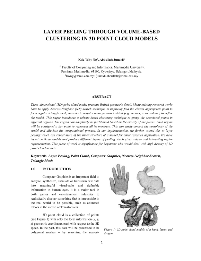
3D point cloud is a collection of points
(see Figure 1) with only the local information (x, y,
z) geometric coordinate, each with respect to the 3D
space. In the past, this data will be processed to be
polygonal meshes -- by searching the nearest-
Figure 1: 3D point cloud models of a hand, bunny and
dragon.
1
neighbor vertices of each point and creating flat
plane associating them. This process is tedious,
time-consuming and difficult to manipulate the
structure of a model for extending it to the other
applications. Moreover, it cannot reveal the internal
structure of the model. In reverse, point cloud
model has all the flexibility to control the level of
detail of a model and easily to display the surfaces
through Q-Splat [1] technique.
used layer peeling to visualize the visible and
invisible parts of the Constructive Solid Geometric
(CSG) model. They computed each depth peeling
and combine them with the surface colors to
synthesize the order-independent transparency for
interactive CSG model. Their model is surface reconstructed. The model-edges are provided prior to
the depth peeling process.
Tagliasacchi et al.[3] applied peeling
process to find the skeleton of an object. With the
normal vector of each point known beforehand,
they cut the features and obtain the relevant
neighborhood points before thinning the object into
skeleton.
To process point cloud, one would apply
computation on each point to acquire more
geometric detail for clustering purpose. However,
this will extremely be time-consuming as each
model may consist of hundreds of thousands of
points or more (see Table 1 in Section 4.0).
Furthermore, some points may overlap or very
close to each other. To compute and render them
will not make much different to the outlook of the
model, but oppositely it could retard the rendering
process and seize a lot of memory and storage. An
act is needed to clump the overlapped points and
only send the significant points for processing.
(a)
Lim et al. [4] peeled the point cloud model
to re-construct the model surfaces. Their algorithm
used the simple k-nearest neighborhood in
constructing the local surfaces. The neighboring
search was computed before they peeled the model
for local convexity.
Evaggelia et al. [6] proposed an accurate
method for voxelizing the polygon meshes. The
voxelization process was always performed before
peeling process took into account. They claimed
that their method was able to eliminate artifacts at
edges and vertices. Their input samples were the
surface meshes with neighboring vertices known.
Zhao et al. [7] exploited their voxelization in
graphics processing units (GPU). They orientated
the model before voxelizing it. For our work, we do
not orientate the object. Hsieh et al. [9] also applied
their work on GPU by finding the distance between
the object primitives and voxels for surface
voxelization.
(b)
Figure 2: (a) Noises appeared in the red box of a dragon.
(b) The enlarged view of the noises at curvature of the
dragon in (a).
In the same time, it is important to also
remove noisy points to boost the accuracy of the
computation process (see Figure 2).
Pavol et al.[8] voxelized the model that
contained sharp details. As voxelization technique
would discretize the continuous surface of the
original object, they applied a priori-detection to
somehow preserve the object shape so that they
were not significantly modified.
Layer peeling is an interesting process. It
reduces any large dimensions into two dimensions.
This will subside to a lot of unwanted constraints
and one may treat any input as an image-based
computation.
2.0
LITERATURE REVIEW
Elmar et al. [10] created the voxelization
of a scene on run time. Their approach handled
both the regular grids and locally optimized grids to
take the advantage of the scene geometry. They
In our survey, layer peeling process is an
important process to separate an object into
different pieces. Marc et al. [2] and Florian et al. [5]
2
extended their approach to shadow volume
clamping. Michael et al. [11] presented data parallel
algorithms for surface and solid voxelization on
graphics hardware.
The Cp will diminish the extra space needed for
voxelization. However, it may not be always within
the point cloud if the points scattered regularly to
all the direction. One can apply Principle Graphs
and Manifolds (PGM) technique [12] to locate Cp
3D Point Cloud
Peeling Process
End
Center Point
Computation
Yes
Voxelization
Assignment on Just-Fit
array. Empty?
Layer
Peeling
Min-Max
Computation
No
Figure 3: Flow chart of our proposed algorithm.
Their algorithm was only stored the close to solid’s
boundary finest level voxels. For those uniform
regions, they were represented by coarse voxels.
3.0
within the points. But we found that it does not
deviate much as we will apply adaptive
voxelization to only cover the spaces that contain
points. Furthermore, PGM is complex and
computation consumption.
PROPOSED ALGORITHM
Below is our proposed algorithm. This
study will discuss how our layer peeling process is
to be carried out.
Next, we will voxelize the points. The size
of the voxel is user-controlled input. We can do this
automatically by limiting each voxel with certain
number of points, but for those dense models, this
will create more than enough voxels as some of
them can be combined with others to ease the
computation process. With the user input, the user
can liberally tune the size that they visually satisfy.
Please refer to the result section for the voxel size
(Figure 6). Besides, we will adaptively voxelize (or
sub-space) the points. Space with no point cloud
will not be voxelized. In the existing methods
discussed in Literature Review section, many
researchers were using uniform grid to voxelize the
points (Figure 4a). This will create a lot of
unnecessary voxels (voxels without containing any
points); this will decelerate the process and waste
of storage. In Figure 4b, we construct the voxels
As mentioned earlier in the abstract, we
will voxelize the point cloud. Now, where should
we start dividing the space and what is the most
suitable voxel size to be applied to classify the
points? We choose to start at the Center point, Cp:
n 1
Pi
Center point, Cp =
i 0
n
where P is the 3D coordinate (xi, yi, zi) and n is the
number of points.
3
along the point cloud with the help of Octree data
structure [13]. Iteratively, it will divide the space
into eight sub-spaces. Each point will be checked of
its current voxel position by using the function,
F(x,y,z) = 4z + 2y + x, where (x,y,z) refers to the
coordinate point. If the current voxel size does not
meet the user-defined threshold, it will further
divide the current voxel. Other unrelated voxels
will remain at its original size. At the end, we will
only store the voxels that meet the threshold and
eliminate the unrelated voxels to relieve the storage.
For processing each layer, we can create a
just-fit array size and assign each voxel directly to
its position in ascending order. The just-fit array
size can be determined by finding the minimum and
maximum value of the center voxels from each
layer (Figure 5). We coded the following
instruction to assign the center voxels into the justfit array. Please be noted that the center voxels are
pre-stored in LayerPeel array. With this, we do not
need to manually search for the nearest neighboring
voxels as they can be found directly on the indices.
(a)
(a)
(b)
(b)
Figure 5: (a) The first layer of the center voxels of the
hand model. (b) We store the voxels in a just-fit array
size with “1” represented the existing voxels and “0”
represented none voxels.
Figure 4: (a) Hand model is voxelized with uniform grid.
Extra voxels are created. (b) We adaptively voxelize the
hand model with Octree data structure.
for ( i = 0; i < LayerPeel.size(); i++)
for ( j = 0; j < LayerPeel[i].size(); j = j+3)
{
DirectAssignX = (LayerPeel[i][j] - minVoxX) / voxelSize + 0.0005;
DirectAssignY = (LayerPeel[i][j+1] - minVoxY) / voxelSize + 0.0005;
JustFitArray[i][DirectAssignY][DirectAssignX] = 1;
}
Instruction 1: This is the fragment code used to assign center voxels directly to its just-fit array.
Layer peeling can access into point cloud
sequentially and efficiently. In uniform grid, this
can simply be acquired through each layer of x-y
plane along the z-dimension. For Octree user, the
center points are stored randomly. Re-sorting each
of them is a huge effort. We propose to store them
in priority queue with respect to z-dimension while
voxelizing the points in our previous step. This will
automatically allocate each voxels in a descending
order. When we peel the voxels, we can simply cut
them off as the layer is different in depth (see
Figure 6). This process is more efficient then
peeling through uniform grid.
In last step, the voxels assignment will
continue if each layer in the priority queue is none
empty. Else, the process will stop and the entire
peeling process is complete.
4.0
RESULT
The original point cloud data and the
voxels used to sub-space the points are listed in the
table below. We have divided the voxels into rough
and fine type. One can use rough voxels to speed up
their process if the model does not contain many
twisted features such as the hand and bunny.
4
Table 1: The three point cloud models are being tested in our experiment. The original numbers of points
are voxelized in rough and fine voxel size.
3D Model
Bunny
Hand
Dragon
Number of
layers applied
33
28
52
Rough voxels
No
%
5,427
15.09
5,932
11.18
30,785
7.03
Number of
vertices
35,947
53,054
437,645
Obviously, in Table 1 the dragon produced
more layers than the other models. This shows that
the point cloud dragon is denser and more
overlapping points occurred. One may argue that
the dragon contains higher number of points and
uses smaller voxel size, therefore it is denser.
Visually, we cannot solely depend on the number of
points or voxel size as the dragon is in fact
occupying more space than the other models. When
we voxelize the point cloud dragon, we have
limited the size to the extent of our perspective. The
second column (in Figure 6) is the maximum extent
which the voxels are completely imitating the
model shape.
REFERENCES
In rough voxels column in Table 1, it
shows the number of voxels being created to
voxelize the points. Although hand model contains
more voxels, it is actually more computation
efficient than bunny model, with respect to the
proportion of the percentage of the voxels to the
number of points of the hand model. This is more
noticeable in fine voxels column.
5.0
Fine voxels
No
%
18,531
51.55
21,028
39.63
104,833
23.95
CONCLUSION
In this study, we have proposed an
efficient layer peeling process to dismantle an
object into different layers without needing to
compute the Nearest Neighboring search or the help
of the normal vector. In future, we can apply the
peeling result to run for other application such as
3D Segmentation, Skeletonization, 3D Shaperetrieval and etc.
ACKNOWLEDGEMENT
The models are obtained from Princeton
University research lab [14] and Stanford
University 3D Scanning Repository [15].
5
[1]
Szymon Rusinkiewicz and Marc Levoy,
“QSplat: A Multiresolution Point Rendering
System
for
Large
Meshes",
SIGGRAPH'2000. pp.343~352.
[2]
Marc Nienhaus, Florian Kirsch and Jürgen
Döllner, "Illustrating design and spatial
assembly of interactive CSG",AFRIGRAPH
'06 Proceedings of the 4th international
conference on Computer Graphics, Virtual
Reality, Visualisation and Interaction in
Africa. 2006, pp.91-98.
[3]
A. Tagliasacchi, H. Zhang, and D. Cohen-Or,
Curve skeleton extraction from incomplete
point cloud, ACM Trans. on Graph, vol. 28,
no. 3, 2009.
[4]
Chi-Wan Lim and Tiow-Seng Tan, "Surface
Reconstruction by Layer Peeling", The
Visual Computer, Pacific Graphics, Taiwan,
vol. 22, pp. 593—603, 2006.
[5]
Florian Kirsch, Marc Nienhaus and Jürgen
Döllner, “Visualizing Design and Spatial
Assembly of Interactive CSG”, technical
report, Universitat of Postsdam, pp1-12,
2005.
[6]
Evaggelia-Aggeliki Karabassi and T.
Theoharis, “A fast depth-buffer-based
voxelization algorithm.” ACM Journal of
Graphics Tools, 4)4_:5-10, 1999.
[7]
Zhao Dong, Wei Chen, Hujun Bao, Hongxin
Zhang and Qunsheng Peng. Real-time
Voxelization for Complex Polygonal Models.
In Proceedings of Pacific Graphics, Seoul,
Korea. pp.73-78, 2004.
Rough voxels
Fine voxels
Bunny
Voxel size: 0.003644
Bunny
Voxel size: 0.001822
Hand
Voxel size: 0.016979
Hand
Voxel size: 0.008489
Dragon
Voxel size: 0.001759
Dragon
Voxel size: 0.000879
Layers Peeling
Figure 6: Rough and fine voxels of the three models (1st column and 2nd column). The remaining columns are the results
of the layer peeling process. The top-left corner shows the starting of the peeling process and the bottom-right shows the
ending of the process.
6
[8]
Pavol Novotný, Leonid I. Dimitrov and Miloš
Šrámek. "Enhanced Voxelization and
Representation of Objects with Sharp Details
in Truncated Distance Fields", IEEE
Transaction on Visualization and Computer
Graphics (vol. 16 no. 3) pp. 484-498, 2010.
[12] A. N. Gorban and A. Y. Zinovyev, “Principal
Graphs and Manifolds” , Handbook of
Research on Machine Learning Applications
and Trends: Algorithms, Methods and
Techniques, Ch. 2, Information Science
Reference, pp.28-59, 2009.
[9]
Hsien-Hsi Hsieh, Chin-Chen Chang, Wen-Kai
Tai and Han-Wei Shen, "Novel Geometrical
Voxelization Approach with Application to
Streamlines". Journal of Computer Science
and Technology Volume 25, Number 5, pp.
895-904, 2010.
[13] Jin Qian and Yongjie Zhang, "Sharp Feature
Preservation in Octree-Based Hexahedral
Mesh Generation for CAD Assembly
Models", Proceedings of the 19th
International Meshing Roundtable, Part 4,
pp.243-262, 2010.
[10]
Elmar Eisemann and Xavier Décoret, "Fast
Scene Voxelization and Applications." ACM
SIGGRAPH, Symposium on Interactive 3D
Graphics and Games, pp71-78, 2006.
[11]
[14]
Suggestive Contour Gallery. Retrieved on 17
February 2013. http://www.cs.princeton.edu/
gfx/proj/sugcon/models/.
[15] The Stanford 3D Scanning Repository.
Retrieved
on
22
February
2013.
http://graphics.stanford.edu/data/3Dscanrep/
Michael Schwarz and Hans-Peter Seidel,
"Fast parallel surface and solid voxelization
on GPUs", ACM Transactions on Graphics,
29, 6 (Proceedings of SIGGRAPH Asia
2010), pp. 179:1–179:9, December 2010.
7
