gwat12398-sup-0001-AppendixS1
advertisement
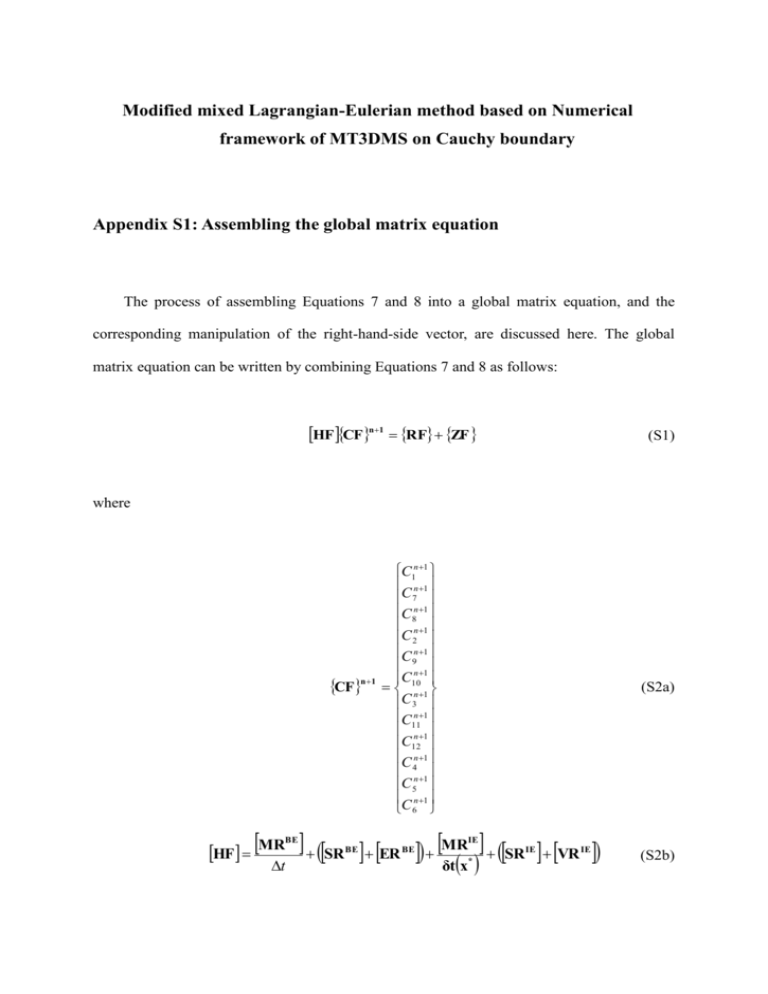
Modified mixed Lagrangian-Eulerian method based on Numerical framework of MT3DMS on Cauchy boundary Appendix S1: Assembling the global matrix equation The process of assembling Equations 7 and 8 into a global matrix equation, and the corresponding manipulation of the right-hand-side vector, are discussed here. The global matrix equation can be written by combining Equations 7 and 8 as follows: HF CFn1 RF ZF (S1) where CFn 1 HF MR BE t C1n 1 n 1 C 7 C8n 1 n 1 C 2 C n 1 9n 1 C 10n 1 C 3 C11n 1 n 1 C12 C n 1 4n 1 C 5 C n 1 6 (S2a) SR ER MR SR VR δt x IE BE BE IE * IE (S2b) RF MR BE t ZF FR BE BR IE CF MR CF δt x IE B n I * (S2c) * FF11,k1 FF11,k1 1,k 1 1,k 2 FF7 0 FF7 FF81,k 2 FF81,k 3 0 1,k 3 BF22 ,k1 FF21,k 3 BF22 ,k1 FF2 BF 2 ,k1 BF 2 ,k 2 0 9 92 ,k 2 2 ,k 3 0 BF10 BF10 2 ,k 3 3 ,k 1 BF3 0 BF3 BF113,k1 BF113,k 2 0 3,k 2 3 ,k 3 0 BF12 BF12 BF 3,k 3 BF 4 ,k1 0 4 44 ,k1 BF55 ,k1 0 BF5 5 ,k 1 5 ,k 1 BF6 BF6 (S2d) In Equation S2d, except for the first, fourth, and last rows, all other terms are zero because FFi e ,k1 and FFi e ,k 2 of the two adjacent elements, ( k1 and k 2 ), contiguous to interior node i , cancel each other out in a finite element approach (Istok 1989). Similarly, BFi e ,k 1 and BFi e ,k 2 are also cancelled out. However, FF21,k 3 and BF22 ,k1 will not be cancelled out because FF21,k 3 is obtained by applying an FEM for fine-mesh element k 3 in global element (1), and BF22 ,k1 is obtained by applying an ELM for fine-mesh element k1 in global element (2), as shown in Figure 1. This can be directly illustrated by including FF21,k 3 and BF22 ,k1 in Equation S3: C C ZF4 FF21,k 3 BF22 ,k1 VC D D VC x x x x x x x x 2 2 2 (S3) Here, it should be noted that because the velocity computation in an FEM is continuous at the elemental interface between global elements (1) and (2) (Yeh 1981; Park and Aral 2007), and the dispersion coefficient is a function of the velocity, the dispersion coefficient is continuous. Therefore, Equation S3 holds. Moreover, VC x x on the right side of 2 Equation S3 can be rewritten as VC x x 2 x2 V x2 C x2 (S4) where V x2 is already known because the flow equation is usually solved in advance. However, Cx2 is unknown and must be solved. Therefore, a fourth row of the global matrix HF and a fourth element ZF should be modified as follows: HF j , j1C8n1 HFj, j C2n1 HF j , j1C9n1 RF j ZFj , j 4 (S5) where HF j, j HF j , j x2 V x2 , j4 (S6a) ZF j ZF j VC xx 0 , j4 (S6b) 2 It should be noted that ZF is modified using Equations S3–S6, so that the fourth row of the load vector becomes zero. So, the load vector modified from ZF is as follows: C VC D FF1 x x 0 0 0 and it can be calculated by using Cauchy boundary 5a and 0 0 BF65 ,k1 D C x x L 1,k 1 Neumann boundary 5b. References Istok, J.D. 1989. Groundwater modeling by the finite element method. Water Resources Monograph no. 13. Washington (DC): American Geophysical Union. Park, C.-H., and M.M. Aral. 2007. Sensitivity of the solution of the Elder problem to density, velocity and numerical perturbations. Journal of Contaminant Hydrology 92, no. 1-2: 33-49. Yeh, G.T. 1981. On the computation of Darcian velocity and mass balance in the finite element modeling of groundwater flow. Water Resources Research 17, no. 5: 1529–1534.
