State diagrams
advertisement
Notes: 011 – State Diagrams
CS/SE3430 / CS5430 - Object-Oriented Analysis and Design
1 State Diagrams
1.1 Deterministic Finite(-state) Automata (DFA),
Deterministic Finite(-state) Automata (DFA), are used to recognize syntax (for instance in parsing
strings of a language for a compiler).
Uses:
Computer Languages
Natural Languages (grammar, syntax, punctuation)
Spell checkers
Dialed telephone numbers to determine how (which circuits) to route them
Internet routers
Object states
Control Systems
Electronic circuits
The formal definition of a DFA is given as the 5-tuple (Q, , , start-state, end-state)
Where:
1. States: Q
2. Alphabet:
3. Transitions
4. Start state
5. End state
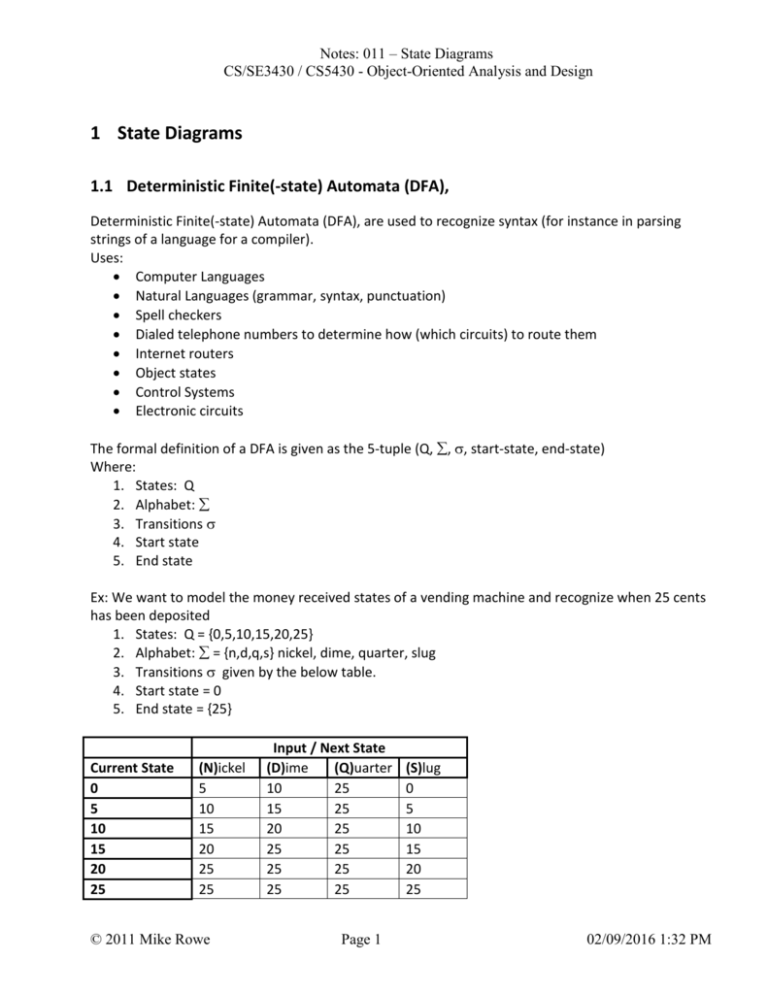
Ex: We want to model the money received states of a vending machine and recognize when 25 cents
has been deposited
1. States: Q = {0,5,10,15,20,25}
2. Alphabet: = {n,d,q,s} nickel, dime, quarter, slug
3. Transitions given by the below table.
4. Start state = 0
5. End state = {25}
Current State
0
5
10
15
20
25
(N)ickel
5
10
15
20
25
25
© 2011 Mike Rowe
Input / Next State
(D)ime
(Q)uarter
10
25
15
25
20
25
25
25
25
25
25
25
Page 1
(S)lug
0
5
10
15
20
25
02/09/2016 1:32 PM
Notes: 011 – State Diagrams
CS/SE3430 / CS5430 - Object-Oriented Analysis and Design
S
0
N
S
D
5
N
S
D
10
N
S
Q
D
15
N
S
20
D
N
D
25
© 2011 Mike Rowe
Page 2
02/09/2016 1:32 PM
Notes: 011 – State Diagrams
CS/SE3430 / CS5430 - Object-Oriented Analysis and Design
Recognize the binary PIN number “1011” -- don’t tell anyone the PIN, it’s a secret.
0
Start
1
1
1
0
0
10
1
0
101
1
1011
1.2 State diagrams
See Chapter 11 of Stevens
Primary purpose of a state diagram is to describe objects that have significant state and complicated
transitions between states. Such as:
Individual GUI objects and even entire dialogs and windows
Objects that model physical objects that have complex state EX: telephones
Control systems that model objects that are being controlled
Objects that model business objects
© 2011 Mike Rowe
Page 3
02/09/2016 1:32 PM
Notes: 011 – State Diagrams
CS/SE3430 / CS5430 - Object-Oriented Analysis and Design
1.3 Four UML State Diagram Symbols
State – represent the possible states of an object.
Transitions – represent legal transitions from one state to another.
Events – the labels of a transition defining under what conditions the transition is used.
Actions – Activities that take place inside of a state.
1.3.1 State
State Markers – rounded rectangle that represents a specific state of an object
o Simple state – cannot be broken down any further
o Composition state – can be broken down into substates. This can be done by Nesting a
state diagram within a state or also by nesting states within a state
Start marker (state) – a big solid dot that represents start here
End marker (state) – a big dot with a circle around it that indicates the end of processing, not all
systems will have an end marker
State1
start
State
end
1.3.2 Transitions
A line with a directional arrow that signifies a change of an object from one state to another
state. Transitions always occur in response to some event.
More than one transition can leave a state: this may be due to events of different messages or
the same message with different guard conditions.
push()
On
Off
push()
hitWithHammer()
hitWithHammer()
Broken
© 2011 Mike Rowe
Page 4
02/09/2016 1:32 PM
Notes: 011 – State Diagrams
CS/SE3430 / CS5430 - Object-Oriented Analysis and Design
1.3.3 Events
A label associated with a transition that identifies the message and/or message and guard
condition which causes a state change.
An event is a function call known to an object: like pushButton( ). It may have parameters:
hitWithHammer( hard ).
Guard conditions can modify the direction of a state change based on conditions placed on one
or more of the message parameters. This allows the same message from a single state go to
multiple different states.
Example: A person’s credit state. We will use three functions makePayment(), charge(), and
close() along with Guard conditions relating to the balance to make transitions.
o payment( amount ) [amount > -balance]
o charge( amount ) [ amount > balance ]
o charge( amount ) [ amount = balance ]
o payment( amount ) [amount > -balance]
payment( amount )
payment( amount ) [amount > -balance]
ou
nt
<
charge( amount ) [ amount > balance ]
en
t
(a
ou
)[
nt
)
ou
ue
am
v al
nt
ge(
m
r
cha
-b
al
an
ce
]
pa
ym
=
=
-b
al
an
ce
]
Account
zeroBalance
ch
charge(amountt)
[amount < balance]
Account
credit
)
)[
am
Account
debit
nt
nt
ou
ou
am
am
nt (
t(
me
en
pa y
pa
ym
am
e(
g
ar
ou
n
[
t)
am
ou
nt
=
ce
an
l
ba
]
close( )
start here
© 2011 Mike Rowe
Page 5
02/09/2016 1:32 PM
Notes: 011 – State Diagrams
CS/SE3430 / CS5430 - Object-Oriented Analysis and Design
Examples to try as a class:
States of a library book.
o On shelf
o Checked out
o Being read
o Open
o Closed
o Returned
o Ready to be shelved.
Two Stop lights (treat as one object)
States (North-South) (East-West)
G
R
Y
R
this and the next state are needed to make
R1
R1
sure the intersection is cleared
R
G
R
Y
R2
R2
G
R
State(location) of passenger going from Germany to Platteville
o Cities, oceans, customs, baggage claim, bus, van, …???
Go to lunch (person) only making 90 degree turns
o Major locations along the way ???
The waterfall process, pick at least 5 levels
Position ( pos = street name )on an outing to 2nd street.
State of a pizza that has been ordered from Y.
Spiral process with exit. (need conditions)
1.3.4 Actions
Actions are changes to attributes within a state. A state can trigger actions in one of five
different ways.
o On entry – an action triggered upon first entering a state
o Do – an action that takes place during the lifetime of the state (starts on entry / stops
upon exit ) EX: timers
o On Event – these actions take place in response to an event. EX: counters
o On Exit – these actions take place in response to exiting an event
o Include – these actions invoke / call a submachine from another state diagram
© 2011 Mike Rowe
Page 6
02/09/2016 1:32 PM
Notes: 011 – State Diagrams
CS/SE3430 / CS5430 - Object-Oriented Analysis and Design
For Entry, Do, Exit and Include the format is action-label / action where action-label is “Entry”,
“Do”, “Exit” or “Include”
For Events the format of an Action is event-name( param ) [ guard-condition ] / actionstatement.
payment( amount ) [amount < -balance]
Debit
payment( amount ) [amount > -balance]
OnEntry: payment( amount ) [amount < - balance ]/ balance += amount
OnEntry: charge( amount ) / balance -= amount
charge( amount ) [ amount < balance ]
charge( amount ) [ amount > balance ]
ym
pa
t(
en
Credit
am
ou
OnEntry: payment( amount )/ balance += amount
OnEntry: charge( amount ) [amount < balance]/ balance -= amount
nt
nt
]
ou
(v
rge
am
cha
)[
t=
un
cha
rge
(
am
o
un
t)
pa ym
[a
mo
e nt( a
ce]
m ou n
bal
t)
e)
lan
-ba
anc
e
a lu
==
Account zeroBalance
OnEntry: balance-= 0.0
close( )
start here
© 2011 Mike Rowe
Page 7
02/09/2016 1:32 PM
Notes: 011 – State Diagrams
CS/SE3430 / CS5430 - Object-Oriented Analysis and Design
1.4 Composite State
A composite state can be divided into substates.
Example: We have a ride share system with a Class called Journey. The “Available” state is
entered when a driver. The “Active” state is entered when someone wants to share a ride.
“Active” state has two substates, “Vacancy” and “Full”. Vacancy indicates that there are seats
available in the car, Full indicates then all seats are full.
removeSharer( )
Active
Available
addSharer( )
endJourney()
endJourney()
Active
remo
veSh
arer(
)[ sha
reC n
Available
addSharer()
[ shareCnt < seats ]
t==
addSharer()
[ shareCnt = = seats ]
0]
addSharer() [ shareCnt = = seats ]
addSharer( )
Vacancy
Full
OnEntry: shareCnt--
OnEntry : shareCnt++
removeSharer()
startTrip( )
endJourney()
startTrip( )
addSharer()
[ shareCnt < seats ]
From the Available state we transition into Active. The start mark in Active has conditions that
reflect the entry into Active, addSharer( ) to direct the transition into the proper substate Vacancy
or Full. Based on seats available we enter either into Vacancy or Full substate. Once in the Active
state riders may drop out to move to Vacancy or more riders may be added to transition to the Full
substate.
Entry into a composite state initiate all start points within a composite.
© 2011 Mike Rowe
Page 8
02/09/2016 1:32 PM
Notes: 011 – State Diagrams
CS/SE3430 / CS5430 - Object-Oriented Analysis and Design
1.5 Concurrent Substates
An object can be in several states at one time. For instance a customer can be in debt and
waiting for a paycheck to come.
A composite state may consist of multiple concurrent substates.
Example: Applying to college requires many tasks, and most of these tasks can be completed
simultaneously rather than needing to be done in a special serial order, for instance: submitting
ACT scores, filling out an application, sending High School transcripts, etc.
Application
PendingACT
PendingHS_T_
Script
receiveAppl()
AppComplete
receiveHS_TS()
PendingMedH
istory
The two tasks submitting ACT scores and submitting HS Transcripts are independent. An
applicant can be in one or both of these states at the same time.
The application composite state will exit when ALL substates complete.
Transactions can go directly into or out of a substate of a composition state.
EX: A student may reapply to UWP after already having been a student. They do not need to
resubmit ACT or HS Transcripts, just fill out another application (and probably pay a fee).
© 2011 Mike Rowe
Page 9
02/09/2016 1:32 PM
Notes: 011 – State Diagrams
CS/SE3430 / CS5430 - Object-Oriented Analysis and Design
Application
PendingACT
receiveAppl()
PendingHS_T_
Script
receiveHS_TS()
AppComplete
receiveApp( )
PendingAppli
cation
Resubmit( )
Reapply( ) [ goodStanding ]
1.6 Synchronization
Rather than having multiple concurrent substates within a composite state we can also have
concurrent states without encapsulating them.
If we do this we need to make sure that each of the states completes before transitioning
downstream in the state machine. This is done with synchronization bars.
Synchronization bars can also be used to make sure that all preconditions have been satisfied
before entering a state.
PendingACT
AppComplete
PendingHS_T_
Script
© 2011 Mike Rowe
Page 10
02/09/2016 1:32 PM
Notes: 011 – State Diagrams
CS/SE3430 / CS5430 - Object-Oriented Analysis and Design
1.7 Decision Point
A decision point allows transitions to be conditionally selected using a diamond symbol
hardWorker
bonusPay()
[ hours >= 50 ]
signTimeCard()
[ hou
rs >=
avgWorker
30 A
ND h
ours
regularPay()
< 50]
[ hours < 30 ]
lightDutyPay()
easyWorker
The transition function is the input to the decision diamond and the conditions/guards are on
the outputs of the decision diamond. The guard conditions determine which path will be taken.
1.8 History State
Sometimes it is useful to reenter a composite state in the same state that you exited it rather
than from an initial state (static attributes).
The symbol for a history store is a ‘H’ inside of a circle connected to one or more substates.
In the below example a washing machine goes from start to washing, to rinsing, to spinning to
done. If the power is cut the washing machine goes to a powerOff state. When the power is
restored the History state remembers what state to resume.
© 2011 Mike Rowe
Page 11
02/09/2016 1:32 PM
Notes: 011 – State Diagrams
CS/SE3430 / CS5430 - Object-Oriented Analysis and Design
1.9 Practice
Progression of a student at UWP (need actions) or Composite states
Fresh, Soph, Junior, Sr BY {1st year, 2nd year, 3rd year)
Placing a telephone call (Phone states) need actions
o On hook
o Off hook
o Dialing
o 5 second inter digit timeout
o Dial long distance – w/ area code (use action to count digits and add to a string)
o Dial prefix (7 digit dialing assumed if not long distance)
o Dial last 4 digits
o Dial 911
o Dial *611
o Dial an operator
o Ringing w/300 second timeout
o Connected A - B
o Call waiting C calls A
o Call holds: B placed on hold then A – C connected
o C on hold, B reconnected with A.
o B hangs up, C connected with A
Registration Procedure with class closing
© 2011 Mike Rowe
Page 12
02/09/2016 1:32 PM
