TEP
5.4.1601
Structural analysis of monocrystals
with the aid of the Laue method
Related topics
Characteristic X-radiation, Bravais lattices, reciprocal lattices, Miller indices, atomic form factor, structure
factor, and Bragg scattering
Principle
Laue diagrams are produced when monocrystals are irradiated with polychromatic X-rays. This method
is primarily used for the determination of crystal symmetries and the orientation of crystals. When a LiF
monocrystal is irradiated with polychromatic X-rays, a characteristic diffraction pattern results. This pattern is photographed and then evaluated.
Equipment
1 XR 4.0 expert unit 35 kV
1 X-ray Plug-in module with W X-ray tube
X-ray Lithium fluoride monocrystal,
1
mounted
1 X-ray Crystal holder for Laue diffraction
1 X-ray Diaphragm tube d = 1mm
1 Vernier caliper, plastic
1 XR 4.0 X-ray film, 100 × 100 mm²
09057-99
09057-80
09056-05
09058-11
09057-01
03014-00
09058-23
1
1
1
3
1
1
1
XR 4.0 X-ray Bag for x-ray films, 10 pieces
X-ray-film developer for 4.5 l
X-ray-film fixing for 4.5 l
Laboratory tray, PP, 18 x 24 cm
X-ray optical bench
X-ray film holder
Slide mount for optical bench, h = 30 mm
09058-22
06696-20
06696-30
47481-00
09057-18
09057-08
08286-01
This experiment is included in the upgrade set “XRS 4.0 X-ray structural analysis”.
Note: This experiment can also be performed with a copper or molybdenum X-ray tube. Instead of the Xray films 09058-23, self-developing x-ray films (9057-20) can be used for the experiment. For more
details, see appendix
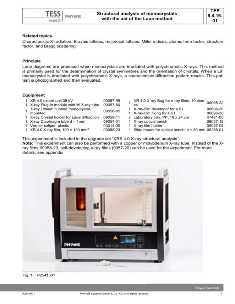
Fig. 1: P2541601
www.phywe.com
P2541601
PHYWE Systeme GmbH & Co. KG © All rights reserved
1
TEP
5.4.1601
Structural analysis of monocrystals
with the aid of the Laue method
Tasks
1. Take a photograph of the Laue pattern of a LiF
monocrystal.
2. Assign the Laue reflections to the lattice planes
of the crystal.
Procedure
Prior to starting the experiment, take the goniometer
out of the experiment chamber.
Then, insert the diaphragm tube with a diameter of
1 mm into the beam outlet of the X-ray plug-in unit.
Add the crystal holder for Laue patterns. Install the
LiF crystal with its two pins in the holder so that the
rounded sides of the crystal holder face the X-ray
tube.
Position the film in darkness in the film holder (see
fig. 2) and confirm that the holder is firmly closed.
Fix the holder into the holder of the fluorescent
screen and position it on the internal optical bench
at a distance D = 1.5-2 cm from the crystal. The
precise determination of this distance is very important for the subsequent evaluation. The film
plane should be parallel to the crystal surface.
The X-ray tube is used at maximum power (anode
voltage UA = 35 kV, anode current IA = 1 mA). In
the case of the tungsten tube, the exposure time is
15-30 minutes. It can be set and activated as follows:
- Select the tube operating parameters and confirm them with “Enter”.
- Under “Menu”, select “Timer” (Fig. 3) → “Duration”. Set the desired time with the aid of the arrow buttons. Confirm with “Enter”.
- The window “Mode” appears. Select “On” and
confirm with “Enter” (Fig. 4).
- To start the experiment, close and lock the sliding door and press the button under “Start”
(Fig. 5).
The irradiation starts. It will stop automatically after
the preset exposure time. On the display, the remaining time can be observed based on a backwards running clock and a display bar.
X-ray films must be developed in a darkroom, following the instructions on the packaging. Then, the
films are rinsed in a water bath before they are
fixed for approximately 10 minutes. After that, the
films are re-watered for 10 minutes and then dried
in the air. Please refer to the instructions of use of
the X-ray film for details concerning their use.
2
Fig. 2: Position of the film in the film holder
„enter“
Fig. 3
Fig. 4
„Start“
Fig. 5
PHYWE Systeme GmbH & Co. KG © All rights reserved
P2541601
TEP
5.4.1601
Structural analysis of monocrystals
with the aid of the Laue method
If you use a molybdenum or copper Xray tube:
- Select an exposure time of at
least 30 minutes.
- In order to be able to see
weaker reflections, select an
exposure time of up to 120
minutes.
Theory
Laue diagrams are produced when monocrystals
are irradiated with polychromatic X-rays. This
method is used mainly for the determination of
crystal symmetries and the orientation of crystals.
A complete analysis of the diagrams is only possible with simple crystal structures.
A necessary, although insufficient, condition for
Fig. 6: Scattering geometry of a Laue pattern. The y-axis
the constructive reflection at the various lattice
is in the plane of the film and is perpendicular to
planes is the Bragg condition:
the x,z plane.
2d sin n ; (n = 1, 2, 3,…)
(1)
(d = interplanar spacing, ϑ = glancing angle, λ = wavelength, and n = 1, 2, 3, ...)
With the lattice constant a of a cubic crystal, the following is valid for the spacing d(hkl) between the individual lattice planes:
d hkl
a
(2)
h k2 l2
2
If L is the distance between a reflection and the centre of the Laue pattern, and D the distance between
the film and the sample (Fig. 6), then the glancing
angle ϑexp that is determined in an experimental
manner is:
1
2
exp arctan
L
;
D
L
y2 z2
(3)
y and z are the distances of the reflection in a system
of rectangular coordinates with its origin in the centre
of the pattern.
If the X-ray beam coincides with a certain crystallographic direction [h*,k*,l*] (here, the [100] direction)
and if it impinges on a crystal plane (h,k,l), then the
angle of incidence α (see Fig. 7) is determined by the
scalar product of the normal vector of the plane and Fig. 7: Reflection on a lattice plane with random orientation.
the incident vector.
www.phywe.com
P2541601
PHYWE Systeme GmbH & Co. KG © All rights reserved
3
TEP
5.4.1601
cos
Structural analysis of monocrystals
with the aid of the Laue method
h
h h * k k * l l *
2
k 2 l 2 h * k * l *
2
2
2
(4)
Then, the following is valid for the glancing angle:
ϑcal = 90° - α.
According to the addition theorem and with
(h*,k*,l*) = (100), it follows from (4) that:
sin
h
h k l
2
2
2
(5)
Evaluation
Task 1: Take a photograph of the Laue pattern of
a LiF monocrystal.
Fig. 8: Laue pattern of the LiF (100) crystal.
Operating values of the tungsten X-ray tube:
Accelerating voltage UA = 35 kV; anode current
Figure 8 shows the Laue diagram of a LiF(100)
IA = 1 mA; distance between the crystal and film
monocrystal with a face-centre cubic crystal latD = 15 mm; exposure time: t = 15 min
tice (fcc). If the diffraction pattern is rotated by
90° around the direction of the primary beam, it is
again brought to coincidence. Since the primary
beam impinges perpendicularly on the (100)-plane Fig. 9: Schematic representation of the Laue reflections.
of the LiF crystal, the crystal direction [100] is a
fourfold axis of symmetry. The intensity of the reflections depends on the reflecting crystal surface
as well as on the spectral intensity distribution of
the X-rays.
Task 2: Assign the Laue reflections to the lattice
planes of the crystal.
The glancing angle ϑcal is calculated from (5) for
all of the planes with low (h,k,l) indices. The angle
ϑexp is determined using (3) based on the diagram.
The assignment of the reflections to the lattice
planes is found when the angles coincide (ϑcal =
ϑexp) and when the condition k/l = y/z is fulfilled,
with z and y being the coordinates of the reflections.
A final control can be performed as follows. In accordance with the Duane-Hunt law of displacement (see experiment P2540901), the beginning
of the bremsspectrum is given by the minimum
wavelength λmin = 1.24∙10-6/UA [m]. For an accelerating voltage UA = 35 kV, the following is true:
λmin = 35.5 pm. This means that for the assignment
of the reflections to the lattice planes, only X-rays
with a wavelength of λ > 35.5 pm can play a role.
4
PHYWE Systeme GmbH & Co. KG © All rights reserved
P2541601
TEP
5.4.1601
Structural analysis of monocrystals
with the aid of the Laue method
Figure 9 shows the location of the reflections in a different manner. For reasons of symmetry, the evaluation can be restricted to 1/8 of the diagram. The other reflections are obtained by permutation of the indices and a change of the sign. Reflection nos. 4 and 8 are only very slightly visible in the original photograph. They can only be seen clearly when a longer exposure time is used.
Table 1 shows the result of the evaluation. It becomes clear that the reflections are visible only if the Miller indices are either all odd or all even. This is a characteristic feature of a face-centred cubic crystal lattice (see experiment 2541301).
Table 1: Evaluation of the Laue diagram
Reflection
no.
1
2
3
4
5
6
7
8
y/mm
x/mm
L/mm
ϑexp /°
hkl
ϑcal /°
k /l
y/ z
d/pm
λ/pm
4.0
0
9.75
6.75
10.75
38.25
7.0
0
12.5
25.5
19.0
6.75
10.75
38.25
34.0
45.75
13.25
25.5
21.25
9.50
15.50
54.50
35.50
45.75
17.29
26.66
24.17
13.34
19.33
53.30
30.75
33.72
113
204
224
133
244
111
315
406
17.55
26.57
24.09
13.26
19.47
35.26
30.47
33.69
0.33
0
0.5
1
1
1
0.2
0
0.32
0
0.51
1
1
1
0.2
0
121.4
100.7
82.2
92.4
90.1
232.6
68.1
55.8
72.2
90.4
67.3
42.6
59.6
268.8
69.6
62.0
Note
In order to keep the relative error as small as possible when determining the distances between the reflections, the following method can be applied. Transfer the diagram to transparent paper and magnify it
twice with the aid of a photocopier. As an option, it is also possible to scan the pattern and to magnify it
on the computer.
www.phywe.com
P2541601
PHYWE Systeme GmbH & Co. KG © All rights reserved
5
TEP
5.4.1601
Structural analysis of monocrystals
with the aid of the Laue method
Taking a Laue photograph with the aid of self-developing X-ray film
A monocrystal X-ray structure analysis can be performed live during a lecture with the aid of selfdeveloping X-ray films (09057-20) in combination
with the XR 4.0 expert unit. If a Cu X-ray tube is
used, the photography only takes 12.5 minutes and,
with molybdenum tubes, good results can be
achieved after just 5 minutes. The development itself takes only 2 to 3 minutes.
Data
Cu X-ray plug-in unit
09057-50
Tube voltage:
35 kV
Beam current:
1 mA
Diaphragm:
1 mm (09057-01)
Exposure time:
10-30 minutes
Set-up in the X-ray unit
The position of the screen is determined with the aid
of the mm scale on the optical bench.
Exposure time: 30 minutes
Screen at 4.7 cm
Exposure time: 20 minutes
Screen at 4.7 cm
Exposure time: 12.5 minutes
Screen at 5.5 cm
The X-ray film is not positioned centrally in front of the crystal. Instead, it is offset, since only a quadrant
of the diagram is sufficient for the evaluation. The picture should be enlarged in order to evaluate it. We
recommend scanning the photo and then enlarging it digitally.
As far as the development of the film is concerned, please refer to the instructions for use that are enclosed with the films. We recommend developing the film for 2 minutes instead of only 50 seconds. It is
very important to hold the developed film under flowing water once it has been taken out of the wrap. Do
not dry it with towels. Only let it air-dry.
6
PHYWE Systeme GmbH & Co. KG © All rights reserved
P2541601

