Fulltext
advertisement
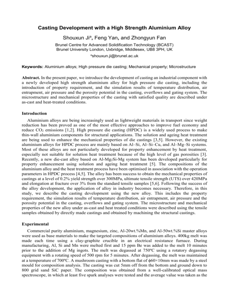
Casting Development with a High Strength Aluminium Alloy Shouxun Jia, Feng Yan, and Zhongyun Fan Brunel Centre for Advanced Solidification Technology (BCAST) Brunel University London, Uxbridge, Middlesex, UB8 3PH, UK a shouxun.ji@brunel.ac.uk Keywords: Aluminium alloys; High pressure die casting; Mechanical property; Microstructure Abstract. In the present paper, we introduce the development of casting an industrial component with a newly developed high strength aluminium alloy for high pressure die casting, including the introduction of property requirement, and the simulation results of temperature distribution, air entrapment, air pressure and the porosity potential in the casting, overflows and gating system. The microstructure and mechanical properties of the casting with satisfied quality are described under as-cast and heat-treated conditions. Introduction Aluminium alloys are being increasingly used as lightweight materials in transport since weight reduction has been proved as one of the most effective approaches to improve fuel economy and reduce CO2 emissions [1,2]. High pressure die casting (HPDC) is a widely used process to make thin-wall aluminium components for structural applications. The solution and ageing heat treatment are being used to enhance the mechanical properties of die castings [3,5]. However, the existing aluminium alloys for HPDC process are mainly based on Al–Si, Al–Si–Cu, and Al–Mg–Si systems. Most of these alloys are not particularly developed for property enhancement by heat treatment, especially not suitable for solution heat treatment because of the high level of gas porosities [3]. Recently, a new die-cast alloy based on Al-Mg2Si-Mg system has been developed particularly for property enhancement using solution and ageing heat treatment [5]. The compositions of the aluminium alloy and the heat treatment process have been optimised in association with the operation parameters in HPDC process [4,5]. The alloy has been success to obtain the mechanical properties of castings at a level of 0.2% yield strength over 300MPa, ultimate tensile strength (UTS) over 420MPa and elongation at fracture over 3% from the standard tensile samples [5,6]. Following the success of the alloy development, the application of alloy in industry becomes necessary. Therefore, in this study, we describe the casting development using the new alloy. This includes the property requirement, the simulation results of temperature distribution, air entrapment, air pressure and the porosity potential in the casting, overflows and gating system. The microstructure and mechanical properties of the new alloy under as-cast and heat treated conditions were described using the tensile samples obtained by directly made castings and obtained by machining the structural castings. Experimental Commercial purity aluminium, magnesium, zinc, Al-20wt.%Mn, and Al-50wt.%Si master alloys were used as base materials to make the targeted compositions of aluminium alloys. 400kg melt was made each time using a clay-graphite crucible in an electrical resistance furnace. During manufacturing, Al, Si and Mn were melted first and 15 ppm Be was added to the melt 10 minutes prior to the addition of Mg ingots. The melt was degassed at 750ºC using a rotatory degassing equipment with a rotating speed of 500 rpm for 5 minutes. After degassing, the melt was maintained at a temperature of 700ºC. A mushroom casting with a bottom flat of 60×10mm was made by a steel mould for composition analysis. The casting was cut 5mm off from the bottom and ground down to 800 grid sand SiC paper. The composition was obtained from a well-calibrated optical mass spectroscope, in which at least five spark analyses were tested and the average value was taken as the chemical composition of the alloy. The measured compositions are 7.05 wt.%Mg2Si, 5.55 wt.%Mg, 0.55 wt.%Mn, 3.54 wt.%Zn and 0.12 wt.%Fe with others <0.1 wt.% and balanced by Al. The castings were produced using a 4500 kN cold chamber high pressure die casting machine, in which most of the operation parameters including injection speed and intensification pressure are monitored. One standard round tensile sample was designed in association with the castings. Therefore, one 6.3mm round tensile sample was made in each shot. The mechanical properties of the casting itself were obtained from a flat tensile sample machined from a specified position in the casting. The flat sample had a cross section of 2.8×6.3 mm with a machined surface on 2.8mm side and casting surface on 6.3mm side. All parameters had been optimized for the HPDC machine during casting trials. The tensile tests were conducted following ASTM standard B557, using an Instron 5500 Universal Electromechanical Testing System equipped with Bluehill software. All tensile tests were performed at ambient temperature. The gauge length of the extensometer was 25 mm and the ramp rate for extension was 2 mm/min. The microstructure of each alloy was examined using a Zeiss optical microscope with quantitative metallography, and a Zeiss SUPRA 35VP SEM. Results and Discussion 340 a b c d 20 The components were supplied as CNC machined parts with a typical wall thickness of 2.8mm. The over size of the casting is 340mm long, 60mm wide and 10mm thick. Most part of the castings has a wall thickness of 2.8mm. The critical area is the shaft, as shown in Fig. 1, which is required to suffer a vertical force of 9kN. The means that the materials yield strength should be over 270MPa if the safety factor is set at 1.5. As such, the specification of the new alloy is targeted at a yield strength over 300MPa, a ultimate tensile strength (UTS) over 400MPa and an elongation over 2%. 16 6 10 Fig. 1 The key dimensions of components. Fig. 2 The casting arrangement in die tools and the position of standard tensile sample in the casting system, (a) temperature distribution, (b) air entrapment, (c) air pressure, and (d) porosity potential at the moment of finishing die filling. In order to replace the CNC machined components with castings, the component structure was modified to the casting requirement, which included to add the parting draft, shrinkage, pin locations, to fill tiny holes and unnecessary features on the surface, and to add extra amount of metals for machining surfaces. After that, the runner system and overflows were added to form the casting structure, as shown in Fig. 2, in which the optimised simulation results by a commercial package was given for the temperature distribution, air entrapment and air pressure in the casting at the moment of finishing melt filling, by which the potential locations of porosity can be identified in the casting. The temperature distribution indicated that the melt temperature was generally in liquid state during cavity filling, only a few locations in the overflows were probably solidified when the melts were fully filled in the cavity. The air entrapment and pressure were mainly associated with the porosity potentials. From the calculation, it was reasonably good as no porosity was seen in the loading area. Therefore, a set of die was made and castings were produced using HPDC process. The typical microstructure and porosity distribution of the directly cast standard tensile samples are shown in Fig. 3 and that of the machined samples from castings are shown in Fig. 4. Unfortunately, the porosity levels were high in the casting. The typical morphology of porosities was irregular in the castings, which were relatively large pores or intergranular cracks in the matrix, as shown in Fig. 5. Consequently, the samples were not able to provide the required mechanical properties under as-cast and heat treatment conditions. Therefore, the further optimisation was carried out. 100μm Fig. 3 Backscattered SEM micrograph showing the distribution of porosity defects on the cross section of the directly cast standard tensile sample. 100μm Fig. 4 Backscattered SEM micrograph showing the distribution of porosity defects on the across section of the die casting. b a 10μm 10μm Fig. 5 SEM micrographs showing the morphology of typical porosity defects in the directly cast standard tensile sample and the die casting, (a) large porosity and (b) intergranular porosity. The modification included to enlarge the size of overflows and to increase the ingate length. The enlarged overflows could capture the forefront melt, which is at a relatively low temperature and may entrap more air. The increase of the ingate length could definitely improve the melt flow patterns during melt filling, in particular for the reduction of turbulence flow in the related areas. After the modification of die structure, the castings were made with optimised parameters. The microstructure and defects distribution are shown in Figs. 6 and 7 for the samples made directly for tensile test and the samples made by machining the castings. It is seen much reduced levels of porosities in comparison with that in Figs. 3 and 4. More importantly, the microstructures shown in Fig. 6 were consistent with the results observed in the early studies [5]. a 100μm b c 10μm 10μm Fig. 6 Backscattered SEM micrograph showing (a) the distribution of porosity defects on the cross section of the directly cast standard tensile sample, (b) the as-cast microstructure at the centre of castings, (c) the as-cast microstructure at the edge of castings. 100μm Fig. 7 Backscattered SEM micrograph showing the distribution of porosity defects on the across section of the die casting. By analysing the phase formation in the casting, the results are shown in Fig. 8. The phases consisted of Al solid solution, eutectic Al-Mg2Si, β-AlMgZn, Mg2Si and α-AlFeMnSi phases. The phases formed in the casting were in agreement with the phases obtained from the equilibrium phase diagram [5]. Therefore, the alloy samples were further heat treated for property enhancement. Fig. 8 Micrograph showing the phase formation in the casting, (1) Al solid solution (white dendrites), (2) eutectic Al-Mg2Si (mix of white Al with blue brown Mg2Si), (3) β-AlMgZn (light brown), (4) Mg2Si (dark), (5) Al15(Fe,Mn)3Si2 (brown-grey). 3μm Fig. 9 Backscattered SEM micrograph showing the microstructure of castings after solution and ageing treatment. a 10 6 200 4 100 2 0 0 As-cast Solution Solution and Ageing 400 Strength (MPa) 8 300 Elongation (%) Strength (MPa) 400 500 12 Yield UTS Elongation Yield UTS Elongation 12 b 10 8 300 6 200 4 100 Elongation (%) 500 2 0 0 As-cast Solution Solution and Ageing Fig. 10 Tensile properties of (a) the machined samples from die castings, and (b) the directly cast tensile samples. Fig. 9 shows the microstructure of die castings after T6 heat treatment at 490ºC for 30 minutes for solutionising and 180ºC for 90 minutes for ageing. It is seen a dissolution of AlMgZn intermetallics and the spheroidisation of Mg2Si in the eutectic microstructure. In comparison with the as-cast microstructure, the difference was apparent, which could result in a significant improvement of mechanical properties. Fig. 10 shows the tensile properties of the samples made by directly-made castings and by machining of castings. It is seen that the solution treatment reduced the yield strength and UTS but increased the elongation. However, the subsequent ageing significantly increased the yield strength and UTS with a reduction of elongation. In comparison with that under as-cast condition, the mechanical properties were obviously improved for the directly cast samples under solution and ageing condition. However, the improvement in the yield strength and UTS were significant for the machined samples, but the improvement in elongation was not very significant, although it was at an acceptable level in industry. This may relate to the casting structure, filling system and casting parameters. Overall, after the solution and ageing, the directly cast samples provided a yield strength of 325MPa and a UTS of 430MPa and an elongation of 4.8% and the machined samples provided a yield strength of 315MPa and UTS of 416MPa and elongation of 2.2%. This is satisfied for the property requirement set by the project, indicating the success of replacing the CNC components with high pressure die castings. Summary 1) The replacement of the CNC machined components with high pressure die castings has been success by using the newly developed high strength aluminium alloy. 2) The directly cast standard tensile samples have a yield strength of 325 MPa and a UTS of 430 MPa and an elongation of 4.8 %, and the machined samples from castings have a yield strength of 315 MPa and UTS of 416 MPa and elongation of 2.2 %. 3) Heat treatment is an effective way to enhance the mechanical properties of the die-cast Al-8Mg2Si-6Mg-3.5Zn alloy. Acknowledgement The authors would like to thank the EPSRC (UK) for financial support under the grant for the EPSRC Centre – LiME and TARF-LCV project. References [1] T. Zeuner, L. Würker. Process Optimisation of Cast Aluminium Chassis Components WFO Technical Forum 2003, p3.1-3.14. [2] S. Ji, D. Watson, Z. Fan, M. White. Development of a super ductile diecast Al–Mg–Si alloy Mat. Sci. Eng. A 556 (2012) 824–833. [3] V. S. Zolotorevskii, N. A. Belov, M. Glazoff. Casting aluminium alloys, first ed., Elsevier, London, 2007, pp. 386-396. [4] F. Yan, S. Ji, Z. Fan. Effect of Cu on the microstructure and mechanical properties of diecast Al-Mg2Si-Mg based alloy Materials Science Forum 794-796 (2014) 172-177. [5] S. Ji, F.Yan, Z. Fan. Development of a high strength Al–Mg2Si–Mg–Zn based alloy for high pressure die casting Mat. Sci. Eng. A 626 (2015)165–174. [6] F. Yan, S. Ji, Z. Fan. Effect of excess Mg on the microstructure and mechanical properties of Al-Mg2Si high pressure die casting alloys. Materials Science Forum 765 (2013) 64-68.

