Laboratory Exercise 7
advertisement
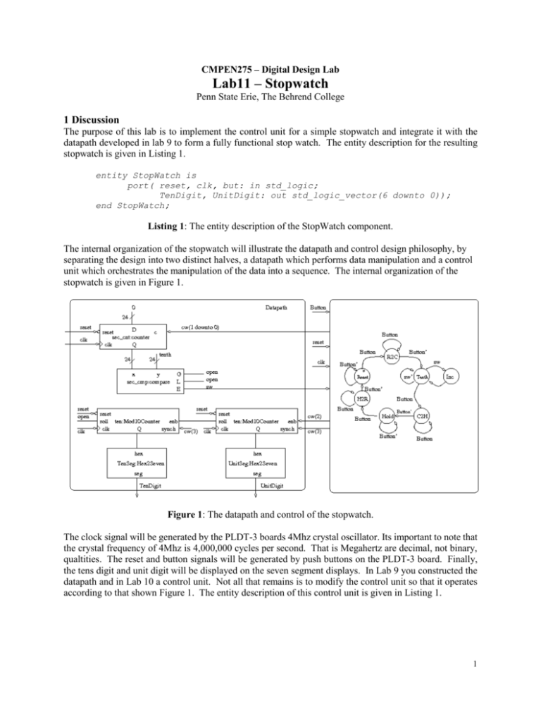
CMPEN275 – Digital Design Lab Lab11 – Stopwatch Penn State Erie, The Behrend College 1 Discussion The purpose of this lab is to implement the control unit for a simple stopwatch and integrate it with the datapath developed in lab 9 to form a fully functional stop watch. The entity description for the resulting stopwatch is given in Listing 1. entity StopWatch is port( reset, clk, but: in std_logic; TenDigit, UnitDigit: out std_logic_vector(6 downto 0)); end StopWatch; Listing 1: The entity description of the StopWatch component. The internal organization of the stopwatch will illustrate the datapath and control design philosophy, by separating the design into two distinct halves, a datapath which performs data manipulation and a control unit which orchestrates the manipulation of the data into a sequence. The internal organization of the stopwatch is given in Figure 1. Figure 1: The datapath and control of the stopwatch. The clock signal will be generated by the PLDT-3 boards 4Mhz crystal oscillator. Its important to note that the crystal frequency of 4Mhz is 4,000,000 cycles per second. That is Megahertz are decimal, not binary, qualtities. The reset and button signals will be generated by push buttons on the PLDT-3 board. Finally, the tens digit and unit digit will be displayed on the seven segment displays. In Lab 9 you constructed the datapath and in Lab 10 a control unit. Not all that remains is to modify the control unit so that it operates according to that shown Figure 1. The entity description of this control unit is given in Listing 1. 1 entity control is Port ( clk, reset : in STD_LOGIC; sw, button : in STD_LOGIC; cw : out STD_LOGIC_VECTOR (3 downto 0)); end control; Listing 2: The entity description of the StopWatch control unit. The stopwatch control unit will issue a different control word in state. The value of the control word will configure the datapath to perform whatever action is required in that state. The stopwatch starts off in the Reset state (thats why it has a “*“ in it) and stays there while the button is not pressed. In the reset state, the control unit instructs the datapath to reset the Mod10Counter and sec_cnt counter. When the button is pressed, the control unit goes to the transistion state R2C, which stands for Reset-to-Count. It waits there until the the button is released at which point the control unit goes to the Tenth state. The control unit waits in the Tenth state until the clock divider count reaches a count value representing 1/10 of a second. When the count values reaches this value then the E output of the comparator will go to one causing the control unit to transition to the Inc state. The control unit spends a single clock cycle in the Inc state, where it tells the datapath to increment the Mod10Counters and reset the clock divider counter. If the user presses the button while the control unit is in the Tenth state the control unit goes to the transistion state C2H, which stands for Count-to-Hold. It waits there until the the button is released at which point the control unit goes to the Hold state. In the Hold state, the control unit tells the clock divider to hold and the Mod10Counters to hold. When the user presses the button the control unit goes to the transistion state H2R, which stands for Hold-to-Reset. When the button is released the control unit transitions back to the Reset state to start the process all over again. 2 In-lab week 1 In the lab you will modify and combine existing files to build your stopwatch. 1. Complete the control word table for the stopwatch control unit in Table 1. State cw(3) cw(2) cw(1 downto 0) Synch Enb Clock divider 0 time unchanged 0 time unchanged 00 hold 1 time=00 1 counting up 01 load 10 count up 11 synch reset Reset R2C Tenth Inc C2H Hold H2R Table 1: The control word table for the stopwatch. 2. Modify the lab 10 control unit for proper operation in the stop watch. o Modify the state_process making it identical to the one depicted in Figure 1. o Modify the output_process creating a control word identical to Table 1. o Run the testbench posted on the class web page. Verify the correct operation of the control unit. Include the following traces in your timing diagram: clk, reset, button, state, and control word bits relabeled to reflect their titles in Table 1 (e.g. relabel cw(3) as Synch). o Run the simulation for at least 8uS. 2 3. Combine the files for the datapath (lab 9) and the control unit from the previous step into a single component for the stopwatch. o Create a stopwatch component which integrates the datapath and control. o Change the “tenth” constant to 5 for the simulation. o Create a testbench for the combined datapath and control. Use the button press statement from the control unit testbench posted on the class web page. o Include the signals from the control unit in your simulation as well as the tenths count (decimal not 7-segment) and the unit count. 4. Use the UCF file from lab9 to create a synthesized stopwatch o Change the “tenth” constant in Figure 1 to a value to generate a 0.1 second delay at 4Mhz. o Synthesize the design o Download and have the instructor verify proper operation of the circuit. 3 In-lab week 2 A formal lab report is due on the last Friday of classes. 3
