A 1.2.6 Airfoil Simulation
advertisement
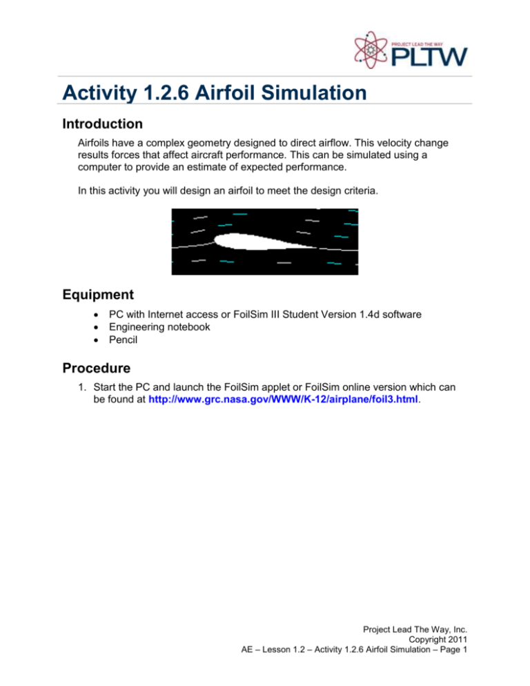
Activity 1.2.6 Airfoil Simulation Introduction Airfoils have a complex geometry designed to direct airflow. This velocity change results forces that affect aircraft performance. This can be simulated using a computer to provide an estimate of expected performance. In this activity you will design an airfoil to meet the design criteria. Equipment PC with Internet access or FoilSim III Student Version 1.4d software Engineering notebook Pencil Procedure 1. Start the PC and launch the FoilSim applet or FoilSim online version which can be found at http://www.grc.nasa.gov/WWW/K-12/airplane/foil3.html. Project Lead The Way, Inc. Copyright 2011 AE – Lesson 1.2 – Activity 1.2.6 Airfoil Simulation – Page 1 2. Design the airfoil to achieve the results given by your teacher. a. Use the geometry assigned by your teacher eg. symmetric, high center, flat plate, flat bottom, negative camber, ellipse or curve plate. b. Change the Lift and Drag to Cl and Cd to compare results. Project Lead The Way, Inc. Copyright 2011 AE – Lesson 1.2 – Activity 1.2.6 Airfoil Simulation – Page 2 c. Your airfoil shape results can be seen graphically using the gauges button as shown below. The final quantitative results are available using the Data tab. 3. Set the First Angle of Attack to -20O and the Final Angle of Attack to 20O and the Angle of Attack Step to 5O. Record the Cl and Cd for each angle of attack. Project Lead The Way, Inc. Copyright 2011 AE – Lesson 1.2 – Activity 1.2.6 Airfoil Simulation – Page 3 Conclusion 1. What parameters impact the Cl and Cd? The wings of the aircraft impact the coefficient of lift and drag. 2. Explain why these have such an impact. The shape of the wings effect the cl and cd. The wing must be able to slice threw the air but have enough drag to stay in flight. The shape of the wing completely dictates that. Project Lead The Way, Inc. Copyright 2011 AE – Lesson 1.2 – Activity 1.2.6 Airfoil Simulation – Page 4


