Lesson 11 (1) Connection of Capacitors in Parallel In a parallel
advertisement
Lesson 11
(1) Connection of Capacitors in Parallel
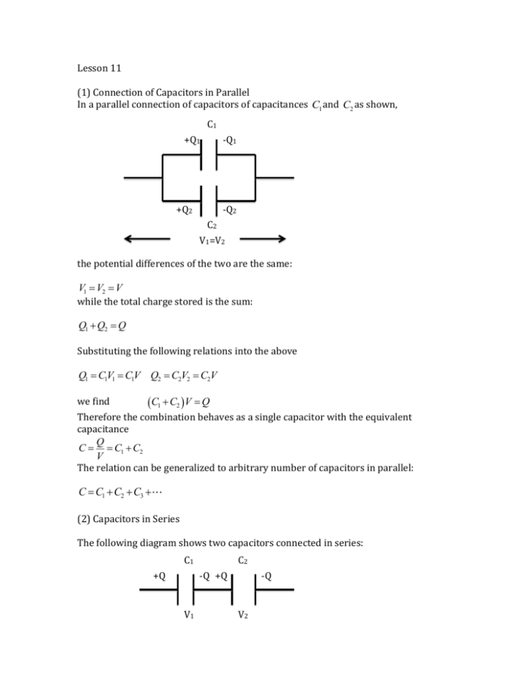
In a parallel connection of capacitors of capacitances C1 and C2 as shown,
C1
+Q1
-Q1
+Q2
-Q2
C2
V1=V2
the potential differences of the two are the same:
V1 = V2 = V
while the total charge stored is the sum:
Q1 +Q2 = Q
Substituting the following relations into the above
Q1 = C1V1 = C1V Q2 = C2V2 = C2V
we find
(C1 + C2 ) V = Q
Therefore the combination behaves as a single capacitor with the equivalent
capacitance
Q
C = = C1 + C2
V
The relation can be generalized to arbitrary number of capacitors in parallel:
C = C1 + C2 + C3 +
(2) Capacitors in Series
The following diagram shows two capacitors connected in series:
C1
+Q
C2
-Q +Q
V1
-Q
V2
The two are initially uncharged, so that the connecting wire connects plates with
opposite charges of the same magnitude Q , which can be considered the stored
charge in the combination. Therefore
Q1 = Q2 = Q
On the other hand, the total potential difference from the left most to the right post
plates is the sum
V1 +V2 = V
Substituting
V1 =
Q1 Q
=
C1 C1
V2 =
we find
Q2 Q
=
C2 C2
æ1 1ö
ç + ÷Q = V
è C1 C2 ø
The combination behaves as a single capacitor with equivalent capacitance C
satisfying
1 V 1 1
= = +
C Q C1 C2
In general, for series combination of an arbitrary number of capacitors,
1 1 1 1
= + + +
C C1 C2 C3
For only two capacitors, we can use
C=
C1C2
C1 + C2
Some networks can be decomposed into series and parallel combinations as the
following example shows.
Example: In the network shown, C1 = 6F, C2 = 3F C3 =12F . A potential difference
V = 8.0V exists between the terminals. Find the charges and potential differences on
each capacitor.
(3) Reconnection of capacitors
When capacitors are charged and then connected, instead of using the rules of series
and parallel combinations to determine the charges and potential differences. we
should analyze the problem using charge sharing and the equalization of potentials
at the points of connection.
Suppose C1 ,C2 carrying charges Q1,Q2 respectively are connected so the positive
plates are connected together as do the negative plates. In the diagram, the positive
plates are denoted by a, c and the negative by b, d .
The capacitors are clearly in parallel, with total charge 𝑄1+𝑄2 . Since the equivalent
capacitance is 𝐶1 +𝐶2 , the final potential difference for both capacitors is
𝑉=
𝑄1 + 𝑄2
𝐶1 + 𝐶2
On the other hand, if the charged capacitors are connected so that the positive plate
of one is connected to the negative plate of the other as shown:
a b
c d
and we wish to find the final potential differences on the individual capacitors, we
cannot use the formula for series connection, which assumes the capacitors to store
the same charge. For the potential differences after the connection, we define
𝑉1, = 𝑉𝑎 − 𝑉𝑏 ,
Because 𝑉𝑎 = 𝑉𝑑
𝑉2, = 𝑉𝑐 − 𝑉𝑑
𝑉𝑏 = 𝑉𝑐 we have
𝑉1, + 𝑉2, = 0
If 𝑄1, , 𝑄2, denote charges on the left plates of each capacitor (rather than the positive
plate), so that −𝑄1, , −𝑄2, are the charges on the right plates, the above equation
leads to
𝑄1, 𝑄2,
+
=0
𝐶1 𝐶2
The total charge on plates 𝑎 and 𝑑should be unchanged after the connection:
𝑄1, − 𝑄2, = 𝑄1 − 𝑄2
We now have two equations for the two unknowns 𝑄1, , 𝑄2,
(4) Dielectric Constant
When a slab of dielectric material is placed in a region where there is a uniform
electric field of strength E0 , induced charges appear on the surfaces of the material
due to polarization. The induced charge produces an induced electric field Eind
in the opposite direction. As a result, the electric field strength inside the material is
reduced, being given by 𝐸 = 𝐸0 − 𝐸𝑖𝑛𝑑 . The dielectric constant is defined by
𝜅=
𝐸0
𝐸
and is a property of the material greater than one. The dielectric strength of the
material is the electric field inside the material when it breaks down. (becoming
conducting)
(5) Dielectric in Capacitors
Consider a parallel plate capacitor of plate area 𝐴 and plate separation 𝑑 with a
dielectric filling up the space between the plates. When charge 𝑄is stored in the
capacitor, it resides on the plates, but not the dielectric. This charge produces the
electric field 𝐸0 in the absence of the dielectric given by
𝐸0 =
𝑄
𝜀0 𝐴
The actual electric field inside the dielectric is
𝐸=
𝐸0
𝑄
=
𝜅
𝜅𝜀0 𝐴
The potential difference between the plates is
𝑉 = 𝐸𝑑 =
𝑄𝑑
𝜅𝜀0 𝐴
The capacitance is
𝐶=
𝑄
𝐴
= 𝜅𝜀0
𝑉
𝑑
Thus, capacitance can be increased by the use of dielectrics.
Let the induced charge on the face of the dielectric in contact with the positive plate
be denoted by −𝑄𝑖𝑛𝑑 . Together with the charge 𝑄on the positive plate, the charges
behave like a sheet charge 𝑄 − 𝑄𝑖𝑛𝑑 on an area 𝐴, with the opposite charge on the
negative plate. The interior electric field is related to these sheet charges by
𝐸=
𝑄 − 𝑄𝑖𝑛𝑑
𝜀0 𝐴
Using the relation between 𝐸 and 𝐸0 , we find
𝑄 − 𝑄𝑖𝑛𝑑
𝑄
=
𝜀0 𝐴
𝜅0 𝜀0 𝐴
Solving for the induced charge:
𝑄𝑖𝑛𝑑 =
𝜅−1
𝑄
𝜅
Example: Find the capacitance of a parallel plate capacitor half filled with a
dielectric in the space between the plates.
Solution: With charge 𝑄 on the plate, the electric field is
𝐸=
{
𝑄
𝜀0 𝐴
𝑄
𝜅𝜀0 𝐴
𝑖𝑛 𝑡ℎ𝑒 𝑣𝑎𝑐𝑢𝑢𝑚 𝑟𝑒𝑔𝑖𝑜𝑛
𝑖𝑛 𝑡ℎ𝑒 𝑑𝑖𝑒𝑙𝑒𝑐𝑡𝑟𝑖𝑐
The potential difference is
𝑉=
𝑄 𝑑
𝑄 𝑑
+
𝜀0 𝐴 2 𝜅𝜀0 𝐴 2
𝐶=
𝑄
2𝜅
𝐴
=
𝜀0
𝑉 𝜅+1 𝑑
The capacitance is

