Lambert´s law of radiation
TEP
2.4.0405
Used concepts
Specific irradiance, beam density, diffuse emission and reflection.
Principle
The diffuse reflection of a sheet of paper is examined according to Lambert’s law of radiation in relation
to characteristic emission of radiation.
Equipment
1
Base plate with rubber feet
1
He/Ne Laser, 5mW with holder*
1
Power supply for laser head 5 mW*
2
Adjusting support 35 x 35 mm
2
Surface mirror 30 x 30 mm
5
Magnet foot
2
Lens support
1
Mounted lens, f = +100 mm
1
Diaphragm support
1
Rotating guide rail with magnet
1
Photocell, silicone
1
Measurement amplifier, universal
1
Voltmeter 0.3 ... 300 V/10 ... 300 V~
2
Connecting cable red, l = 500 mm
1
Sheet of paper
*Alternative equipment
1
HeNe laser
08700-00
08701-00*
08702-93*
08711-00
08711-01
08710-00
08723-00
08021-01
08724-00
08717-00
08734-00
13626-93
07035-00
07361-01
08180-93
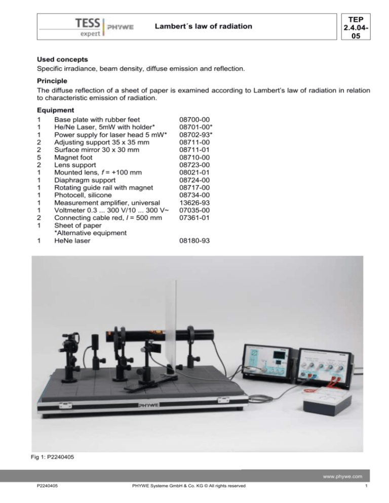
Fig 1: P2240405
www.phywe.com
P2240405
PHYWE Systeme GmbH & Co. KG © All rights reserved
1
TEP
2.4.0405
Lambert´s law of radiation
Fig. 2: Experimental set up for the qualitative verification of Lambert’s law of radiation (* only required for 5 mW laser)
Set-up and performance
The experimental set up is shown in fig. 1 and 2. The recommended set up height (height of beam
path) should be 130 mm.
A sheet of paper is inserted in the diaphragm support.
The laser beam is adjusted with the mirrors M1 and M2 in such a way that it impinges perpendicularly
on the surface of the paper and on the rotation axis of the rotating guide rail.
Light intensity is measured as a function of the angle by means of photocell LD on the rotating guide
rail.
The smallest adjustable angle φ which can be
comprehended between the perpendicular to
the surface of the paper (that is, the direction
of incidence of the laser beam) and the direction of the detector (cf. fig. 3) is 15°.
After the laser has warmed up for about half
an hour, the experiment should be carried out
in a darkened room, in order to keep luminous
intensity constant.
At the beginning of measurement, an adequate amplification is selected on the universal measurement amplifier (voltage should not
be higher than the maximum output voltage of
10 V).
The laser beam is interrupted and zero adjustment is carried out on the universal measurement amplifier.
Angle φis adjusted between 15° and 80° in
Fig. 3: Diagram of the principle of measurements
steps of 5° with the assistance of the rotating
with the used magnitudes (with O* as apguide rail and the angular scale. The correparent magnitude of surface O)
2
PHYWE Systeme GmbH & Co. KG © All rights reserved
P2240405
Lambert´s law of radiation
-
-
TEP
2.4.0405
sponding intensities (or respectively voltages U(φ)) are measured.
For the sake of precision, the measurement should be repeated several times under the same conditions and voltages U(φ) should be averaged.
Set up of the rotating unit: to begin with, the stop screw of a magnet foot is removed. The circular orifice of the rotating guide rail is pushed over the foot. Furthermore, the angular scale is set over the
magnet foot, above the rotating guide rail. The magnet foot is fastened to the optical base plate, the
rotating guide rail being sufficiently mobile. Photocell LD can then be set at the centre of the rotating
guide rail by means of a magnet foot. Angular distribution should be sensible when set up is made
on the optical base plate, that is, the 0° scale line should point in the direction of the incident laser
beam.
Theory and evaluation
The emission characteristic of a diffusely reflecting surface O is determined by the fact that every surface
element dO scatters incident light uniformly in all directions. This is the case, e. g., for a sheet of paper
consisting of a large number of thin and transparent cellulose fibres. As the beam density L of a diffusely
reflecting surface is constant, to the observer, the total surface O appears to have the same luminosity
whatever direction it is being looked at from. In fig. 3 it can however be seen, that the apparent surface
which is seen by the observer varies with the angle of observation φ. In the boundary case, φ = 90° the
apparent surface vanishes and thus also the irradiation E perceived by the observer. As photocell LD only can ”see” a small angle with its slit orifice, and as the receiving surface remains constantly at the same
distance and perpendicular to the direction of observation during the whole measurement, influences
due to the used reception surface may be neglected in the present case (that is, the radiation intensity E
of the photocell is proportional to beam intensity I of the reflecting surface). In general, Lambert’s cosine
law is valid for the reflecting surface:
where I: beam intensity
and L: beam density (= constant)
Under the given circumstances, one then obtains the following relation of proportionality:
Irradiance intensity E is proportional to the measured voltage U of the photocell (cf. table 1).
The following relation is used for evaluation:
the smallest adjustable angle φ is 15°. According to equation (2), the smallest angle and an arbitrary angle φare related by the fact that E(15°) ~ cos(15°) and E(φ) ~ cosφ. This leads to
When plotting
www.phywe.com
P2240405
PHYWE Systeme GmbH & Co. KG © All rights reserved
3
TEP
2.4.0405
Lambert´s law of radiation
one should obtain a straight line of slope 1 (cf. fig.
4). The plot shows that this is true for the largest angular area. It also is shown that luminous intensity is
too high for small angles. In this area, one receives a
directly reflecting proportion which is not radiated diffusely. This shows that a smooth sheet of paper is
no ideal Lambert radiator (the result improves with
increasing roughness).
Fig. 4: Plot for the confirmation of Lambert’s law.
For this, voltages U(φ) were normalised
with the value of U(15°) and cos(φ) with
cos (15°)
Table 1: Voltage U(φ) as a function of angle at the photocell, with corresponding angular adjustments
φ
U(φ):Volt 2.75 2.58 2.43 2.30 2.10 1.80 1.65 1.47 1.33 1.05 0.88 0.62 0.62 0.33 0.12
20
25
30
35
40
45
50
55
60
65
70
75
75
80
φ:Degrees 15
4
PHYWE Systeme GmbH & Co. KG © All rights reserved
P2240405


