23) ZoomLensesAndMirrors(4-10
ECEN 4616/5616 4/10/2013
Zoom Lens Methods:
From the 2-lens combination equation, 𝐾 = 𝐾
1
+ 𝐾
2
− 𝑑𝐾
1
𝐾
2
, we can see how to make a variable focal length lens by adjusting the distance, d , between two other lenses.
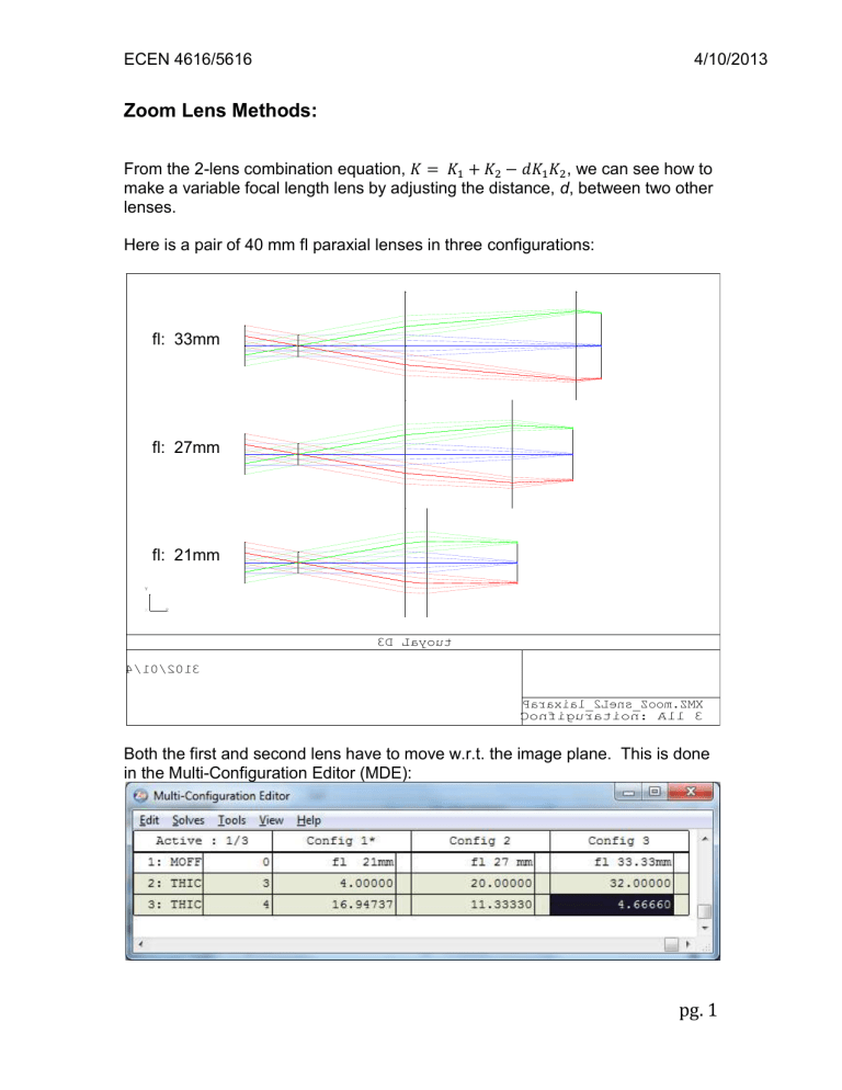
Here is a pair of 40 mm fl paraxial lenses in three configurations: fl: 33mm fl: 27mm fl: 21mm
Y
X Z
3 D L a y o u t
4 / 1 0 / 2 0 1 3
P a r a x i a l _ 2 L e n s _ Z o o m .
Z M X
C o n f i g u r a t i o n : A l l 3
Both the first and second lens have to move w.r.t. the image plane. This is done in the Multi-Configuration Editor (MDE): pg. 1
ECEN 4616/5616
Here is the spot diagram for all three configurations:
4/10/2013
S u r f a c e : I M A
F u l l F i e l d S p o t D i a g r a m
4 / 1 0 / 2 0 1 3 U n i t s a r e µ m .
R M S r a d i u s :
G E O r a d i u s :
S c a l e b a r : 2 e + 0 0 4
4 4 1 6 . 1 6
6 1 3 8 . 6 4
R e f e r e n c e : C h i e f R a y
P a r a x i a l _ 2 L e n s _ Z o o m . Z M X
C o n f i g u r a t i o n : A l l 3
Mechanical ly, it is often convenient if the BFL doesn’t change. One way this can be done is by using an afocal zoom followed by a fixed focusing lens:
The afocal part (from Wikipedia): pg. 2
ECEN 4616/5616 4/10/2013
Typically, K
1
= K
2
, and |𝐾
3
| > 𝐾
1
+ 𝐾
2
. The dashed lines indicate the motion of
L
1
and L
2
as the lens zooms. L
3
is fixed.
To achieve a finite focal length, we only have to add a final focusing lens of arbitrary power:
Of course, each lens can be replaced by a compound set of lenses in order to control aberrations. Often complex-looking zoom systems are rather simple when the lens groups are identified.
The Zemax Zoom lens example (in the “Examples\Zoom Lenses” folder) looks like this:
Y
X Z
3 D L a y o u t
Z o o m l e n s , 2 9 7 8 m m , e m b o d i m e n t 4 , 4 9 3 6 6 6 1
4 / 1 0 / 2 0 1 3
Z o o m l e n s .
z m x
C o n f i g u r a t i o n : A l l 3
Examination of the layout (and the MDE), however, reveals that this lens is functionally equivalent to our two lens zoom system above: pg. 3
ECEN 4616/5616 4/10/2013
Zoom Example:
This is an aerospace company’s missile tracking camera lens. The design goals were to have a 7.5X zoom range, and diffraction limited imaging over both the visible and near IR (600 nm total bandwidth).
Optically, the lens is relatively simple:
The first and last lenses are doublets, and there is a three-lens group in the middle that does most of the focal length change.
The design of this lens probably went like this:
1. The designers reviewed a number of previous zoom designs.
2. Based on the design review, the layout and lens powers were chosen to give the required zoom range in the paraxial approximation.
3. The lens sizes were determined to match the data throughput to the detector.
4. The doublets were defined paraxially to correct chromatic focal shift.
5. The glasses, thicknesses, and shapes of the middle group were chosen to balance the primary third order aberrations.
6. A lens design program was used to refine the lens shapes and determine the detailed movements required to get satisfactory imaging over the zoom range.
The movement was divided into 10 positions, where the design program evaluated the imaging properties for each potential solution. Both the lens parameters and the exact positions were variables for the program to optimize.
This is the movement chart for the final lens:
Notice that all three groups have to move, and two of them have to change direction during the zoom. pg. 4
ECEN 4616/5616
Sounds complicated, but they have a simple solution:
4/10/2013
The three lens groups (center row) slide within a sleeve (bottom). The lens mounts have cam levers that protrude through slots in the sleeve that allow them to slide back and forth over the required range, while maintaining axial alignment.
The lens+sleeve assembly fits into a housing (top) with curved slots that engage the cam levers. When the sleeve is rotated w.r.t. the housing, the lens groups are driven in a pattern determined by the shape of the curved slots.
The assembled lens looks like this: pg. 5
ECEN 4616/5616 4/10/2013
Prism and Mirror Systems:
In the Sequential Mode (which is the easiest to use, as long as you can specify the order in which optical elements are encountered by input rays), Zemax models mirrors by using a “surface” called the “Coordinate Break”.
It is worth reading the manual on this surface, just to get an idea what it is trying to do. Using it, however, is easier learned by looking at the systems in the
“Zemax\Samples\Sequential\Tilted systems & prisms” folder, and to try making some yourself.
There is a (relatively) new feature in Zemax under the menu “Tools\Modify\Add fold mirror”. Here is a simple paraxial lens, with a dummy surface halfway between the lens and the focal plane (surface 3):
Y
X Z
4 / 1 0 / 2 0 1 3
3 D L a y o u t
F o l d e d S y s t e m .
Z M X
C o n f i g u r a t i o n 1 o f 1 pg. 6
ECEN 4616/5616
When we use the “Add fold mirror” dialog box:
We get the following result:
4/10/2013
Y
X Z
3 D L a y o u t
4 / 1 0 / 2 0 1 3
F o l d e d S y s t e m .
Z M X
C o n f i g u r a t i o n 1 o f 1
Note that Zemax has added a thickness to the mirror. This is just cosmetic, and has no effect on ray propagation. pg. 7
ECEN 4616/5616
Here is a complex beamsplitter system, and its specification::
4/10/2013
The beamsplitter is first entered as a transparent plate (surfaces 4 & 5). On the second pass, it is a front surface mirror (surface 11). The small decenter values are cosmetic, meant to position the beamsplitter mirror and plate surfaces in the alignment they would have in the real instrument. pg. 8


