IEC White Paper Fina.. - Heat Pipe Technology, Inc.
advertisement

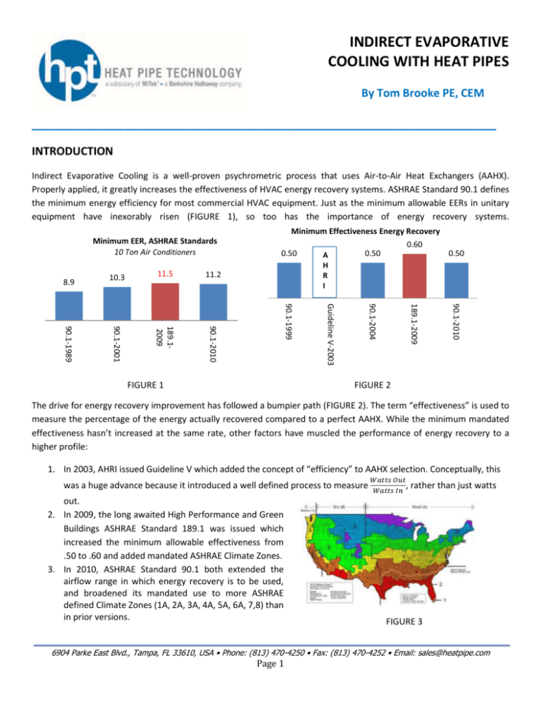
INDIRECT EVAPORATIVE COOLING WITH HEAT PIPES By Tom Brooke PE, CEM __________________________________________________________________ INTRODUCTION Indirect Evaporative Cooling is a well-proven psychrometric process that uses Air-to-Air Heat Exchangers (AAHX). Properly applied, it greatly increases the effectiveness of HVAC energy recovery systems. ASHRAE Standard 90.1 defines the minimum energy efficiency for most commercial HVAC equipment. Just as the minimum allowable EERs in unitary equipment have inexorably risen (FIGURE 1), so too has the importance of energy recovery systems. Minimum Effectiveness Energy Recovery Minimum EER, ASHRAE Standards 10 Ton Air Conditioners 0.50 0.50 90.1-2010 189.1-2009 90.1-2004 FIGURE 1 A H R I Guideline V-2003 11.2 90.1-1999 90.1-2001 90.1-1989 11.5 90.1-2010 10.3 189.12009 8.9 0.60 0.50 FIGURE 2 The drive for energy recovery improvement has followed a bumpier path (FIGURE 2). The term “effectiveness” is used to measure the percentage of the energy actually recovered compared to a perfect AAHX. While the minimum mandated effectiveness hasn’t increased at the same rate, other factors have muscled the performance of energy recovery to a higher profile: 1. In 2003, AHRI issued Guideline V which added the concept of “efficiency” to AAHX selection. Conceptually, this was a huge advance because it introduced a well defined process to measure out. 2. In 2009, the long awaited High Performance and Green Buildings ASHRAE Standard 189.1 was issued which increased the minimum allowable effectiveness from .50 to .60 and added mandated ASHRAE Climate Zones. 3. In 2010, ASHRAE Standard 90.1 both extended the airflow range in which energy recovery is to be used, and broadened its mandated use to more ASHRAE defined Climate Zones (1A, 2A, 3A, 4A, 5A, 6A, 7,8) than in prior versions. 𝑊𝑎𝑡𝑡𝑠 𝑂𝑢𝑡 , 𝑊𝑎𝑡𝑡𝑠 𝐼𝑛 rather than just watts FIGURE 3 6904 Parke East Blvd., Tampa, FL 33610, USA • Phone: (813) 470-4250 • Fax: (813) 470-4252 • Email: sales@heatpipe.com Page 1 DISCUSSION AND BENEFITS While the terms Direct Evaporative Cooling (DEC) and Indirect Evaporative Cooling (formerly known as IDEC and now defined in ASHRAE Fundamentals as IEC) appear similar, they are actually very different. DEC is not an energy recovery technology as defined by ASHRAE or AHRI. Introducing water directly into the airstream cools the air by an adiabatic process. It’s used mostly in arid regions (generally defined by the DRY B ASHRAE climatic zones) where the 100% outside air used in the process has a low enough absolute humidity ratio to allow for adding moisture while still supplying air to a conditioned space for comfort as defined by ASHRAE Standard FIGURE 4 55. While the dry bulb temperature is reduced, FIGURE 4 shows that the enthalpy (total heat content) remains the same and the absolute dew point is increased. On the other hand, IEC introduces water into a separate, counterflow airstream upstream of an AAHX that in the summer transfers only sensible energy from the cooling airstream to an exhaust airstream. Adiabatically evaporating the water upstream of the AAHX reduces the dry bulb temperature which provides a larger delta T and additional heat sink for the heat removed from the cooling airflow. For designers, it is critical to note that the separate airstream can be building exhaust, fresh outside air or process exhaust, just so long as its evaporative cooled dry bulb is lower than the primary cooling airflow. For any given AAHX, the same effectiveness applied to a larger delta T will increase the BTUH transfer. FIGURE 5 shows that both the dry bulb temperature and enthalpy are reduced, while dew point remains the same. In the winter, water is not used so the system reverts to a simple sensible BTUH exchange. Both DEC and IEC each have their applications and the processes can even be combined in series with the outside air entering the IEC first. FIGURE 5 6904 Parke East Blvd., Tampa, FL 33610, USA • Phone: (813) 470-4250 • Fax: (813) 470-4252 • Email: sales@heatpipe.com Page 2 Now let’s evaluate a simple example with the design conditions shown in FIGURE 6. Both airflows are 10,000 CFM and for simplicity we’ll neglect the motor heat. There is space in the Air Handling Unit (AHU) for a 6 row, 12 fpi heat pipe AAHX and evaporative pad upstream of the AAHX. A small pump within the AHU either recirculates water over an evaporative pad (preferred) upstream of the heat pipe in the exhaust air stream or a tree sprays water over the heat pipe. Since water is evaporated in the process, a make-up water supply is needed, and provision should also be made for chemical treatment depending on the local water quality. Because the exhaust heat pipes are constantly exposed to near saturation conditions, they should have a stainless casing and depending again on the local water quality possibly an anti-corrosion coating. Just as in non-IEC applications, provision must also be made for upstream exhaust air filtration and drainage within the compartment. Finally, the designer should remember to take the airside pressure drop of the pads into account in the fan and motor selection. All other components in the AHU are typical. Pressure: 29.9213 inches of mercury eg F 50 80 era t ure -d 40 em p ) (a nt /lb ati o tu tu r Sa 30 HPSupply EA Lvg 60 EA Ent Volu Reheat % 40 % ) 13.5 lb(a 40 u.ft/ 40 10 0.010 -c me 60 14.0 8 0% CW Coil 50 14.5 EvapCooled 20 50 OA 70 Humidity ratio - lb/lb(a) -B py al th 15.0 En 0.020 12.5 13.0 20% 30 40 FIGURE 6 50 60 70 80 Dry bulb temperature - deg F 90 100 110 120 FIGURE 7 6904 Parke East Blvd., Tampa, FL 33610, USA • Phone: (813) 470-4250 • Fax: (813) 470-4252 • Email: sales@heatpipe.com Page 3 The system designer has the ability and the responsibility of presenting alternatives to the owner, and today, the second question the owner will ask is “How much will it cost to operate?” (The first question is “How much will it cost?”). When dealing with coils and air flows, one traditional alternative is to reduce the coil face velocity, and we also want to evaluate IEC, so FIGURE 8 summarizes these alternatives. Selection Std PD (500 fpm) Low PD (400 fpm) No IEC IEC No IEC IEC Leaving Conditions Effectiveness Supply Air (Supply Air) DB/WB 84.6/74.3 .52 79.6/72.9 .77 84.0/74.1 .55 78.7/72.7 .81 Total Airside Pressure Drop “ 1.27 1.42 .87 .96 Recovery Efficiency Ratio (RER) 16.1 19.9 25.3 29.6 MBH Cooling Load Reduction with IEC 56.7 56.2 Notes: Evaporative pads have 80% Effectiveness, fan and motor efficiencies are .80 and .90 respectively FIGURE 8 Recovery Efficiency Ratio (RER) was introduced by AHRI Guideline V – 2003, and is the premier metric by which to compare HVAC AAHX. Whereas “effectiveness” measures the BTUH transfer of a particular AAHX against its theoretical maximum, “RER” is a ratio of the power saved (BTUH) divided by the power used (pressure drop and all other auxiliary power uses). Conceptually, RER is directly comparable to COP and is also dimensionless. In this example, both the effectiveness and RER include, where applicable, the evaporator pad pressure drop and its pump wattage in their calculations. As expected, a lower face velocity provides a higher RER and a superior technical selection (without yet considering economics). Adding the capital costs to a Life Cycle Cost Analysis will reveal the better total selection. Here we see the first key benefit of IEC: IEC saves operating costs, increases the system’s efficiency, and can be used by itself or in conjunction with a lower face velocity. Appropriate measuring sticks are the efficiency as measured by RER for an AAHX and COP for a typical air cooled RTU. It is impressive that the AAHX’s efficiency is almost ten times higher than the RTU. It is evident then that while the RERs are only for the energy recovery system, the fact that all alternatives are higher than the compressor driven system, the HVAC’s total system efficiency will be increased. Another trend suggests itself: if space allows, dual AAHX can be used to decrease the face velocity still further. We can use AHRI Standard 410 which specifies a minimum face velocity of 200 fpm for forced circulation coils as the lower limit before laminar flow must be considered. The second key benefit of IEC is the reduction in the peak load. The last column shows the reduction that the compressor driven portion of the HVAC system with its lower efficiency will not have to meet. The more the load can be shifted onto other devices such as IEC, the more holistically efficient the system will be. And the fact that peak demand can be shaved (and therefore building a power plant can be delayed or eliminated) is the reason why many power companies offer incentives for indirect, direct, and combined evaporative cooled systems. In the example above, IEC stretches the dry energy recovery system’s savings by another 46%. It’s a nice bonus that these conditions occur in the summer when there’s also sometimes a demand surcharge levied by the power company. 6904 Parke East Blvd., Tampa, FL 33610, USA • Phone: (813) 470-4250 • Fax: (813) 470-4252 • Email: sales@heatpipe.com Page 4 The third key benefit of IEC is that these systems are in the mid-mature product life stage. The psychrometric processes are well known. There is good competition among the many manufacturers of the complete package. The owner and engineer don’t have to feel obligated to only one manufacturer but instead can rest easy knowing they’ll be getting the best value for their dollars. The fourth key benefit of IEC is that it is applicable throughout the US. Contrary to popular belief, arid regions of the world aren’t the only places that can benefit from IEC. While the savings aren’t as dramatic, say, in the humid southeast US, they are still significant. FIGURE 8 The fifth key benefit of IEC is that it saves more energy as the ambient increases. This is a characteristic of all sensible AAHX because the BTUH transfer is dependent on the difference in dry bulb temperature between the air streams entering the two AAHX surfaces; a greater difference linearly increases the BTUH transfer. A compressor driven system reduces its BTUH capacity as the ambient increases. The sixth key benefit of IEC is that it is environmentally friendly. Not even HFCs are used, so IEC can’t contribute to climate problems. The seventh key benefit of IEC is that it is particularly suitable for those applications with a higher than normal load Sensible Heat Ratio. The reason is that there isn’t any dew point depression in the IEC process itself. Without the ability to remove moisture, it’s best for applications such as data centers, computer rooms and other selected high sensible process applications. Sure, a local DX or chilled water coil from the central plant can be (and usually is) installed to promote latent cooling and “just in case”. BARRIERS The system designer should be aware that there are still some residual concerns about IEC. Modeling software is not as easily available or third party verified. Water quantity is often restricted in those very climates where IEC works best, although it can be argued that more water is used in the remote generation of electricity. While local water quality can be hard or have high concentrations of minerals and salts, there is a lot of interest in this subject and probably the best answers can be obtained locally from the “old timers”. Building codes usually do not allow for the peculiarities of IEC, nor are there national standards, regulations or certifying agencies. First cost tends to be a little higher than a compressor driven unit of the same tonnage. Typically, the higher required air flow rates means more space and a more robust design is needed. There is a general perception that more maintenance is needed, although that’s open for question. Legionnaire’s disease is sometimes thought to be related to evaporative cooling, but ASHRAE has published Guideline 12 to refute that, especially with IEC systems. 6904 Parke East Blvd., Tampa, FL 33610, USA • Phone: (813) 470-4250 • Fax: (813) 470-4252 • Email: sales@heatpipe.com Page 5 ADVANCES IN IEC These are exciting times for IEC and many designers are quickly grasping the advantages of innovative practices. FIRST, the “old rules of thumb” were that energy recovery applications should be split into those that can tolerate contaminants flowing from the exhaust air back into the incoming fresh air from outside, and those that cannot. The former uses an AAHX that transferred sensible plus latent energy like an enthalpy wheel or membrane plate. While there is inherent contaminant transfer within the latent exchange, there’s also good BTU value in that latent exchange; this tradeoff is acceptable for many applications. The latter uses an AAHX that transfers sensible energy only such as a heat pipe or sensible plate. These medical, laboratory and manufacturing process applications were so sensitive to cross contamination from the exhaust air stream to the incoming fresh air stream that the BTU gain from the latent exchange was given up. However, the intersecting interests of the new ASHRAE Climatic Zones, RER, first costs and concerns for keeping maintenance costs down are upsetting that old paradigm. Designers are now using heat pipe AAHX in more applications once the sole domain of energy wheels, especially in drier regions. Look for documentation supporting that in the near future at www.heatpipe.com. SECOND, the more advanced heat pipe manufacturers have introduced heat pipes that greatly relieve the old physical building limitations of heat pipes. In the past, building designers could only use sensible heat pipes and plates when the building design located the exhaust air stream adjacent and counterflow to the outside air stream; no longer! Advances in the last ten years now allow energy recovery to be used in many more facilities. Heat pipes are now also installed with adjacent parallel airflows (FIGURE 9), separated and on different levels (FIGURES 10 and 11. AIR FLOW AIR FLOW AIR FLOW AIR FLOW AIR FLOW AIR FLOW FIGURE 9 FIGURE 10 FIGURE 11 6904 Parke East Blvd., Tampa, FL 33610, USA • Phone: (813) 470-4250 • Fax: (813) 470-4252 • Email: sales@heatpipe.com Page 6 THIRD, IEC is also used (FIGURE 12) to enhance the system characteristics of the heat pipe wrapped around a cooling coil to provide additional latent removal and/or reduced energy usage by using the heat pipes to provide free precooling and reheating. This system is well established as valuable system alternatives when the application suits. Like the indirect and dry energy recovery examples above, this application requires an exhaust air stream to act as a heat sink in the summer. Different from the wrap around heat pipe however, it provides a constant leaving dry bulb eliminating the need for a trimming reheat coil in critical applications. FIGURE 12 CONCLUSIONS IEC with heat pipes is routine, practical, growing, eliminates cross contamination, provides a higher efficiency and is therefore usually economically justified. Because they contain no moving parts and have inherent simplicity, heat pipes have better reliability and lower maintenance costs than nearly any other component in the HVAC system. 6904 Parke East Blvd., Tampa, FL 33610, USA • Phone: (813) 470-4250 • Fax: (813) 470-4252 • Email: sales@heatpipe.com Page 7


