el_makdissy
advertisement
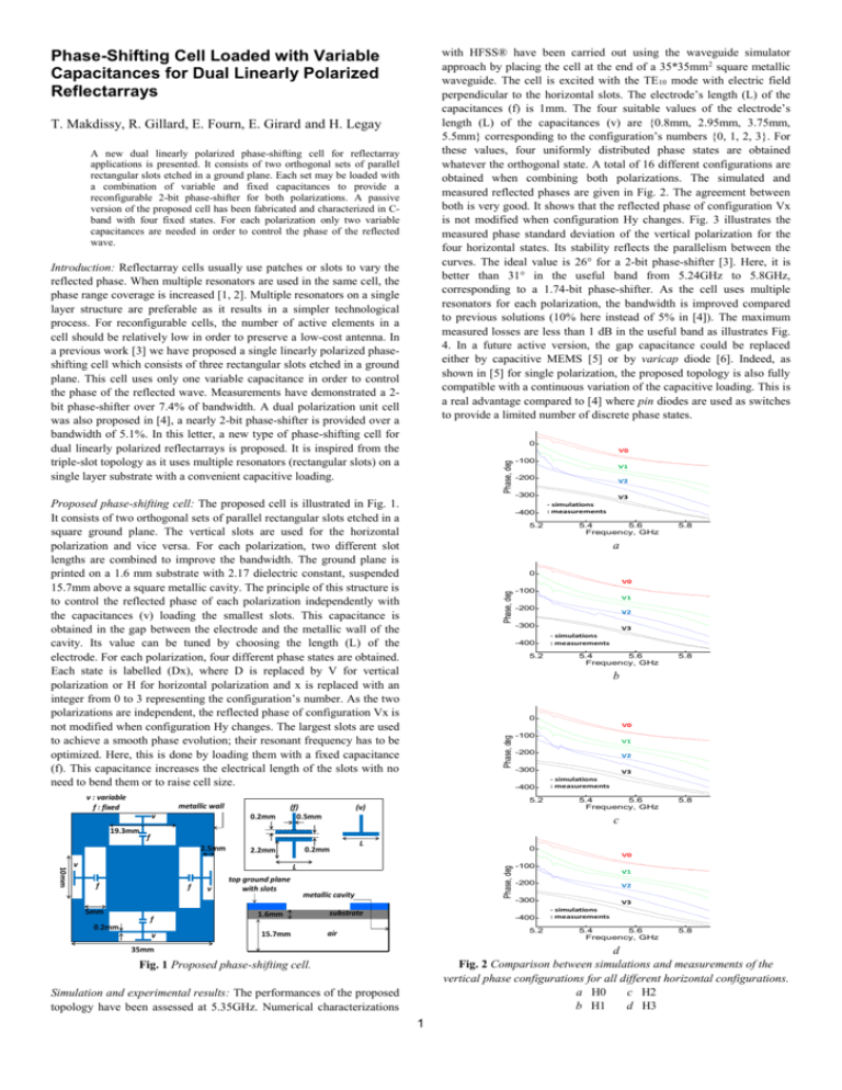
with HFSS® have been carried out using the waveguide simulator
approach by placing the cell at the end of a 35*35mm2 square metallic
waveguide. The cell is excited with the TE10 mode with electric field
perpendicular to the horizontal slots. The electrode’s length (L) of the
capacitances (f) is 1mm. The four suitable values of the electrode’s
length (L) of the capacitances (v) are {0.8mm, 2.95mm, 3.75mm,
5.5mm} corresponding to the configuration’s numbers {0, 1, 2, 3}. For
these values, four uniformly distributed phase states are obtained
whatever the orthogonal state. A total of 16 different configurations are
obtained when combining both polarizations. The simulated and
measured reflected phases are given in Fig. 2. The agreement between
both is very good. It shows that the reflected phase of configuration Vx
is not modified when configuration Hy changes. Fig. 3 illustrates the
measured phase standard deviation of the vertical polarization for the
four horizontal states. Its stability reflects the parallelism between the
curves. The ideal value is 26° for a 2-bit phase-shifter [3]. Here, it is
better than 31° in the useful band from 5.24GHz to 5.8GHz,
corresponding to a 1.74-bit phase-shifter. As the cell uses multiple
resonators for each polarization, the bandwidth is improved compared
to previous solutions (10% here instead of 5% in [4]). The maximum
measured losses are less than 1 dB in the useful band as illustrates Fig.
4. In a future active version, the gap capacitance could be replaced
either by capacitive MEMS [5] or by varicap diode [6]. Indeed, as
shown in [5] for single polarization, the proposed topology is also fully
compatible with a continuous variation of the capacitive loading. This is
a real advantage compared to [4] where pin diodes are used as switches
to provide a limited number of discrete phase states.
Phase-Shifting Cell Loaded with Variable
Capacitances for Dual Linearly Polarized
Reflectarrays
T. Makdissy, R. Gillard, E. Fourn, E. Girard and H. Legay
A new dual linearly polarized phase-shifting cell for reflectarray
applications is presented. It consists of two orthogonal sets of parallel
rectangular slots etched in a ground plane. Each set may be loaded with
a combination of variable and fixed capacitances to provide a
reconfigurable 2-bit phase-shifter for both polarizations. A passive
version of the proposed cell has been fabricated and characterized in Cband with four fixed states. For each polarization only two variable
capacitances are needed in order to control the phase of the reflected
wave.
Introduction: Reflectarray cells usually use patches or slots to vary the
reflected phase. When multiple resonators are used in the same cell, the
phase range coverage is increased [1, 2]. Multiple resonators on a single
layer structure are preferable as it results in a simpler technological
process. For reconfigurable cells, the number of active elements in a
cell should be relatively low in order to preserve a low-cost antenna. In
a previous work [3] we have proposed a single linearly polarized phaseshifting cell which consists of three rectangular slots etched in a ground
plane. This cell uses only one variable capacitance in order to control
the phase of the reflected wave. Measurements have demonstrated a 2bit phase-shifter over 7.4% of bandwidth. A dual polarization unit cell
was also proposed in [4], a nearly 2-bit phase-shifter is provided over a
bandwidth of 5.1%. In this letter, a new type of phase-shifting cell for
dual linearly polarized reflectarrays is proposed. It is inspired from the
triple-slot topology as it uses multiple resonators (rectangular slots) on a
single layer substrate with a convenient capacitive loading.
0
Phase, deg
V0
Proposed phase-shifting cell: The proposed cell is illustrated in Fig. 1.
It consists of two orthogonal sets of parallel rectangular slots etched in a
square ground plane. The vertical slots are used for the horizontal
polarization and vice versa. For each polarization, two different slot
lengths are combined to improve the bandwidth. The ground plane is
printed on a 1.6 mm substrate with 2.17 dielectric constant, suspended
15.7mm above a square metallic cavity. The principle of this structure is
to control the reflected phase of each polarization independently with
the capacitances (v) loading the smallest slots. This capacitance is
obtained in the gap between the electrode and the metallic wall of the
cavity. Its value can be tuned by choosing the length (L) of the
electrode. For each polarization, four different phase states are obtained.
Each state is labelled (Dx), where D is replaced by V for vertical
polarization or H for horizontal polarization and x is replaced with an
integer from 0 to 3 representing the configuration’s number. As the two
polarizations are independent, the reflected phase of configuration Vx is
not modified when configuration Hy changes. The largest slots are used
to achieve a smooth phase evolution; their resonant frequency has to be
optimized. Here, this is done by loading them with a fixed capacitance
(f). This capacitance increases the electrical length of the slots with no
need to bend them or to raise cell size.
v : variable
f : fixed
metallic wall
v
19.3mm
0.2mm
(f)
0.5mm
5mm
0.2mm
f
f
v
v
top ground plane
with slots
15.7mm
5.4
5.6
Frequency, GHz
5.8
0
Phase, deg
V0
-100
V1
-200
V2
-300
-400
5.2
V3
- simulations
: measurements
5.4
5.6
Frequency, GHz
5.8
b
0
Phase, deg
V0
-100
V1
-200
V2
-300
-400
5.2
L
V3
- simulations
: measurements
5.4
5.6
Frequency, GHz
5.8
0
V0
metallic cavity
1.6mm
V3
- simulations
: measurements
a
L
f
V2
-300
5.2
Phase, deg
10mm
v
-200
c
0.2mm
2.2mm
V1
-400
(v)
f
2.5mm
-100
substrate
-100
V1
-200
-400
5.2
air
35mm
V2
-300
V3
- simulations
: measurements
5.4
5.6
Frequency, GHz
5.8
d
Fig. 2 Comparison between simulations and measurements of the
vertical phase configurations for all different horizontal configurations.
a H0
c H2
b H1
d H3
Fig. 1 Proposed phase-shifting cell.
Simulation and experimental results: The performances of the proposed
topology have been assessed at 5.35GHz. Numerical characterizations
1
Phase Standard Deviation, deg
60
T. Makdissy, R. Gillard and E. Fourn (Université Européenne de
Bretagne, INSA, IETR, UMR 6164, F-35708 Rennes, France)
55
50
H0
H1
H2
H3
45
40
E-mail: Tony.Makdissy@insa-rennes.fr
E. Girard and H. Legay (Thales Alenia Space, 26, Av. Jean Francois
Champollion, 31037 Toulouse Cedex 1, France)
35
References
30
25
5.2
5.4
5.6
Frequency, GHz
1.
J. Encinar and J. Agustin Zornoza, “Broadband design of threelayer printed reflectarrays,” IEEE Trans. Antennas Propag., vol.
51, no. 7, pp. 1662-1664, Jul. 2003
2.
M. R. Chaharmir, J. Shaker, and H. Legay, “Broadband Design of
a Single Layer Large Reflectarray Using Multi Cross Loop
Elements,” IEEE Trans. Antennas Propag., vol. 57, no. 10, pp.
3363–3366, Oct. 2009
3.
T. Makdissy, R. Gillard, E. Fourn, E. Girard, H. Legay, “Tripleslot phase-shifting cell loaded with one variable capacitance for
reflectarray applications,” ELECTRONICS LETTERS, Vol. 48,
no. 8, pp. 426-427, 12th April 2012
4.
R. Pereira, R. Gillard, R. Sauleau, P. Potier, T. Dousset and X.
Delestre, “Four-state dual polarisation unit-cells for reflectarray
applications,” ELECTRONICS LETTERS, Vol. 46, no. 11, 27th
May 2010
5.
T. Makdissy, R. Gillard, E. Fourn, E. Girard, H. Legay, “Tripleslot phase-shifting cell loaded with capacitances for reflectarray
applications,” European Conference on Antennas and Propagation
EuCAP 2012, Prague, 26-30 March 2012
6.
L. Boccia, G. Amendola, and G. Di Massa, “Performance
improvement for a varactor-loaded reflectarray element,” IEEE
Trans. Antennas Propag., 2010, 58, (2), pp. 585-589
5.8
Fig. 3 Phase standard deviation of the vertical polarization measured
for all different horizontal configurations.
0
losses, dB
-0.5
-1
V0
V1
V2
V3
-1.5
-2
-2.5
-3
5.2
5.4
5.6
Frequency, GHz
5.8
a
0
losses, dB
-0.5
-1
V0
V1
V2
V3
-1.5
-2
-2.5
-3
5.2
5.4
5.6
Frequency, GHz
5.8
b
0
losses, dB
-0.5
-1
V0
V1
V2
V3
-1.5
-2
-2.5
-3
5.2
5.4
5.6
Frequency, GHz
5.8
c
0
losses, dB
-0.5
-1
-1.5
-2
V0
V1
V2
V3
-2.5
-3
5.2
5.4
5.6
Frequency, GHz
5.8
d
Fig. 4 Measured losses for all different horizontal configurations.
a H0
c H2
b H1
d H3
Conclusion: In this letter, a new dual linearly polarized phase-shifting
cell for reflectarrays has been proposed. It uses two sets of slots loaded
with a combination of fixed and variable capacitances to control the
phase of the reflected wave. Measurements and simulations have
demonstrated that the phase varies quite linearly with frequency and
that the two polarizations are independent. The modification of the
capacitance’s (v) value is sufficient to provide 4 uniformly distributed
phase states with low losses and low dispersion in the two polarizations
on nearly 10% of bandwidth.
2

