here - SIGMA
advertisement
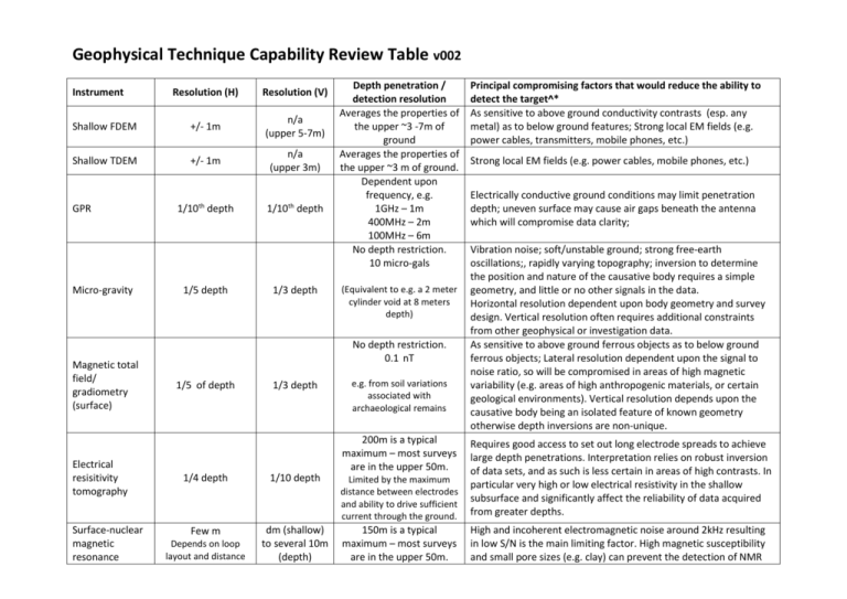
Geophysical Technique Capability Review Table v002 Instrument Resolution (H) Resolution (V) Shallow FDEM +/- 1m n/a (upper 5-7m) Shallow TDEM +/- 1m n/a (upper 3m) 1/10th depth 1/10th depth GPR Micro-gravity Magnetic total field/ gradiometry (surface) Electrical resisitivity tomography Surface-nuclear magnetic resonance 1/5 depth 1/3 depth Depth penetration / detection resolution Averages the properties of the upper ~3 -7m of ground Averages the properties of the upper ~3 m of ground. Dependent upon frequency, e.g. 1GHz – 1m 400MHz – 2m 100MHz – 6m No depth restriction. 10 micro-gals (Equivalent to e.g. a 2 meter cylinder void at 8 meters depth) No depth restriction. 0.1 nT 1/5 of depth 1/3 depth e.g. from soil variations associated with archaeological remains 200m is a typical maximum – most surveys are in the upper 50m. Principal compromising factors that would reduce the ability to detect the target^* As sensitive to above ground conductivity contrasts (esp. any metal) as to below ground features; Strong local EM fields (e.g. power cables, transmitters, mobile phones, etc.) Strong local EM fields (e.g. power cables, mobile phones, etc.) Electrically conductive ground conditions may limit penetration depth; uneven surface may cause air gaps beneath the antenna which will compromise data clarity; Vibration noise; soft/unstable ground; strong free-earth oscillations;, rapidly varying topography; inversion to determine the position and nature of the causative body requires a simple geometry, and little or no other signals in the data. Horizontal resolution dependent upon body geometry and survey design. Vertical resolution often requires additional constraints from other geophysical or investigation data. As sensitive to above ground ferrous objects as to below ground ferrous objects; Lateral resolution dependent upon the signal to noise ratio, so will be compromised in areas of high magnetic variability (e.g. areas of high anthropogenic materials, or certain geological environments). Vertical resolution depends upon the causative body being an isolated feature of known geometry otherwise depth inversions are non-unique. 1/4 depth 1/10 depth Limited by the maximum distance between electrodes and ability to drive sufficient current through the ground. Requires good access to set out long electrode spreads to achieve large depth penetrations. Interpretation relies on robust inversion of data sets, and as such is less certain in areas of high contrasts. In particular very high or low electrical resistivity in the shallow subsurface and significantly affect the reliability of data acquired from greater depths. Few m dm (shallow) to several 10m (depth) 150m is a typical maximum – most surveys are in the upper 50m. High and incoherent electromagnetic noise around 2kHz resulting in low S/N is the main limiting factor. High magnetic susceptibility and small pore sizes (e.g. clay) can prevent the detection of NMR Depends on loop layout and distance (NMR) between measurements Depth of penetration is limited by loop size and Electrically conductive ground conditions signals. Electrically conductive ground conditions (<100 Ohmm) affect the sensitive volume and thus need to be considered during inversion. ^All techniques seek to detect physical contrasts (density, elastic or electrical) between the target object and the surrounding ground materials. Greater contrasts are more easily detected, as are larger, shallower targets. Deeper, smaller and less contrasting targets are correspondingly more difficult to detect. *All anomalies of interest may be masked by the signals/responses generated by other features in the subsurface (or for some technologies also above surface) that may represent equivalent or greater contrasts, and which would therefore mask or compromise the signal detectable from the target feature.


