Full-wave Rectifier with Center-Tapped Transformer Half
advertisement
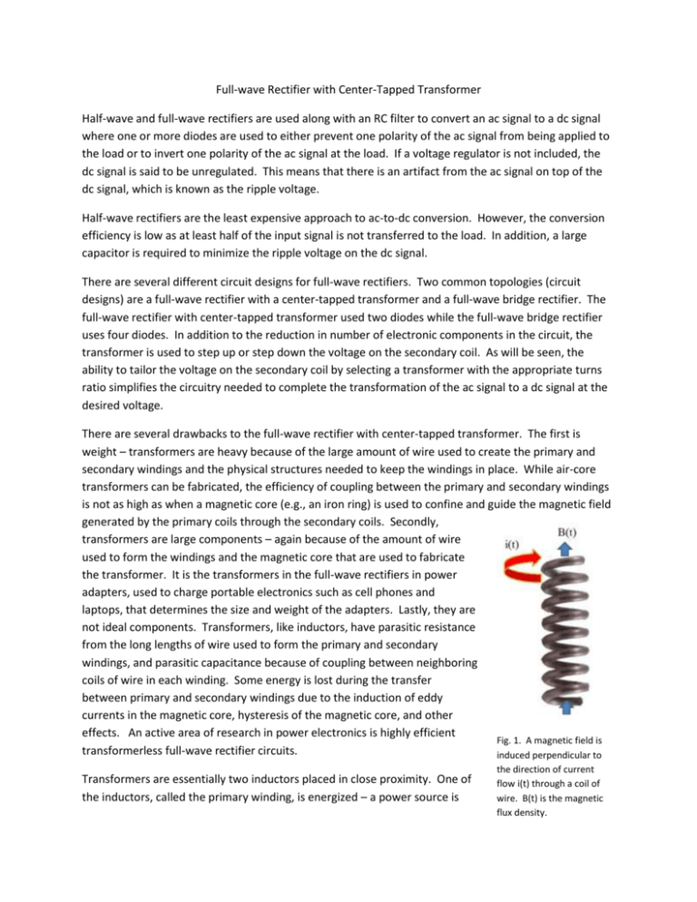
Full-wave Rectifier with Center-Tapped Transformer Half-wave and full-wave rectifiers are used along with an RC filter to convert an ac signal to a dc signal where one or more diodes are used to either prevent one polarity of the ac signal from being applied to the load or to invert one polarity of the ac signal at the load. If a voltage regulator is not included, the dc signal is said to be unregulated. This means that there is an artifact from the ac signal on top of the dc signal, which is known as the ripple voltage. Half-wave rectifiers are the least expensive approach to ac-to-dc conversion. However, the conversion efficiency is low as at least half of the input signal is not transferred to the load. In addition, a large capacitor is required to minimize the ripple voltage on the dc signal. There are several different circuit designs for full-wave rectifiers. Two common topologies (circuit designs) are a full-wave rectifier with a center-tapped transformer and a full-wave bridge rectifier. The full-wave rectifier with center-tapped transformer used two diodes while the full-wave bridge rectifier uses four diodes. In addition to the reduction in number of electronic components in the circuit, the transformer is used to step up or step down the voltage on the secondary coil. As will be seen, the ability to tailor the voltage on the secondary coil by selecting a transformer with the appropriate turns ratio simplifies the circuitry needed to complete the transformation of the ac signal to a dc signal at the desired voltage. There are several drawbacks to the full-wave rectifier with center-tapped transformer. The first is weight – transformers are heavy because of the large amount of wire used to create the primary and secondary windings and the physical structures needed to keep the windings in place. While air-core transformers can be fabricated, the efficiency of coupling between the primary and secondary windings is not as high as when a magnetic core (e.g., an iron ring) is used to confine and guide the magnetic field generated by the primary coils through the secondary coils. Secondly, transformers are large components – again because of the amount of wire used to form the windings and the magnetic core that are used to fabricate the transformer. It is the transformers in the full-wave rectifiers in power adapters, used to charge portable electronics such as cell phones and laptops, that determines the size and weight of the adapters. Lastly, they are not ideal components. Transformers, like inductors, have parasitic resistance from the long lengths of wire used to form the primary and secondary windings, and parasitic capacitance because of coupling between neighboring coils of wire in each winding. Some energy is lost during the transfer between primary and secondary windings due to the induction of eddy currents in the magnetic core, hysteresis of the magnetic core, and other effects. An active area of research in power electronics is highly efficient Fig. 1. A magnetic field is transformerless full-wave rectifier circuits. induced perpendicular to Transformers are essentially two inductors placed in close proximity. One of the inductors, called the primary winding, is energized – a power source is the direction of current flow i(t) through a coil of wire. B(t) is the magnetic flux density. connected to it. As shown in Fig. 1, a magnetic field is induced, the direction of which is determined by the direction of current flowing around the wire coils (recall the right-hand rule). The induced magnetic field is coupled into the second inductor, or secondary winding, because the coils of wire in the secondary winding are located within the magnetic field produced by the primary winding. However, this is an extremely weak coupling and little of the energy stored in the inductor on primary side is transferred to the inductor on the secondary side. Rather, the magnetic field produced by the primary winding is guided through the center of the wire coils of the secondary winding by a magnetic core, the gray rectangle in Fig. 2. Fig. 2. The ratio of the number of turns or coils of wire on the primary side of the transformer, Np, divided by the number of turns on the secondary side, Ns, is called the turns ratio, a, which is 1:1 in this drawing. A center-tapped transformer has two sets of coils on either the primary or secondary side. The transformer in the parts kit has two sets of coils on both the primary and secondary side. The two sets of coils on the primary side, which has three pins, are wired such that the two coils of wire are in series. The two sets of wire coils on the secondary sides are not in series, but are independent of one another (Fig. 3). To create the connections required for the full-wave rectifier circuit shown below, you will have to short the two middle pins on the secondary side together. Fig. 3. Wiring of the primary and secondary coils for the 7 pin transformer in the parts kit. The schematic for the full-wave rectifier with center-tapped transformer is shown in Fig. 4. Note that the components in the path from point C to F and then to D is the same as in a half-wave rectifier as are the components in the path from point E to F and then to D. Fig. 4. Schematic of a full-wave rectifier with center-tapped transformer. 1. Construct the circuit show above. To avoid damaging the transformer, do not apply a voltage to the primary side of the transformer before connecting the diodes and resistor on the secondary side. Note that the longer pin on a packaged diode is connected to the p-side of the diode and the shorter pin is connected to the n-side. You may also be able to see a triangular shaped dish inside the LED package. The LED chip is bonded to the center of the dish. The dish helps direct the light emitted by the LED upwards, out through the plastic lens of the package. 2. Select a sine wave on the arbitrary function generator. Set the amplitude to 5V and the offset to 0V. The frequency of the sine wave should be within the operating specification of the transformer, which is an audio transformer. A frequency of 1 kHz is appropriate. 3. Measure the output of the arbitrary function generator and the voltage between the outer two pins on the secondary side of the transformer, points C and E on the schematic. The ratio of the voltage across the primary side of the transformer divided by the total voltage across the secondary side of the transformer is equal to the turns ratio of the transformer. 4. Measure the voltage across the two secondary coils, the voltage between points C and D and the voltage between E and D, where the negative input terminal of the oscilloscope is connected to point D during both measurements. Record the maximum magnitude of the voltage in both measurements. 5. Measure the voltage across the load resistor where the negative input terminal of the oscilloscope is connected to point D during both measurements. Record the maximum voltage across the load resistor. 6. Note that the voltage across the resistor is zero during some portion of the 1 ms cycle of the input voltage. Determine the range of voltages across one of the secondary windings when VRload = 0 V. 7. Calculate the turn-on voltage Von of the diodes. This is equal to the difference in the voltages recorded in Step 4 and 5. It is also equal to the maximum voltage on one of the secondary windings when VRload = 0 V as measured in Step 6. 8. Look at the power adapter for your lap top computer. The output voltage should be written on it. What turns ratio for a transformer is required for your lap top power adapter if you were to use the LEDs used in this experiment? Note that we commonly say that the ac voltage supplied at a wall plug is 120 V. This is the root-mean squared voltage, VRMS, not VM in the equation VM sin(t). To determine VM, you have to divide VRMS by √2⁄2
