variations indicates
Simulated Effect of Epitaxial Growth Variations on the Gain of SiGe/Ge
Quantum Cascade Lasers
Pavlo Ivanov 1 , Alex Valavanis 2 , Zoran Ikonic 2 and Robert W. Kelsall 2
1 University of Sheffield, North Campus, Broad Lane, Sheffield, S3 7HQ, UK. Email: p.ivanov@sheffield.ac.uk
2 University of Leeds, Woodhouse Lane, Leeds, LS2 9JT, UK. Email: R.W.Kelsall@leeds.ac.uk
Quantum Cascade Lasers (QCLs) are efficient sources of THz radiation. Virtually all modern terahertz
QCLs are GaAs-based devices with maximum operating temperatures below 200 K. Si has a higher thermal conductivity than GaAs and InP and this, combined with the absence of polar optical phonon scattering in Si and Ge, implies that Ge/SiGe QCLs, if realised, would have higher operating temperatures.
The actual thickness of epitaxially grown Ge and SiGe layers normally differs from the designed thickness. Although this growth error can be tolerated in case of conventional quantum-well (QW) laser diodes, the operation of QCLs relies heavily on selective injection of carriers into the lasing state, and efficient carrier extraction to maintain a population inversion. Efficiencies of these processes depend on precise alignment of energy levels in adjacent quantum wells, which depends on the exact layer thicknesses. Thus, the performance of QCLs is much more sensitive to growth variations. It is therefore important to determine the tolerable variation of layer thicknesses before the epitaxial growth is performed, in order to establish the targets for the growth calibration process.
In this work we simulate the performance of three n-doped SiGe/Ge QCL designs in order to investigate the effect of systematic epitaxial-growth errors upon the optical gain of the laser. The active region of each simulated QCL includes 25 –150 periods, each of which consists of a sequence of Ge quantum wells (QWs) and Si
0.15
Ge
0.85
barriers. The three designs contained either 6, 7 or 8
QWs per period, with layer widths specified in nanometres as follows:
6-QW: 5.3/ 1.1
/16.6/ 1.3
/12.3/ 0.3/1.0/0.3
/10.3/ 0.9/1.0/0.9
/7.1/ 0.7/1.0/0.7
/7.8/ 4.3,
7-QW: 5.6/ 1.1
/15.9/ 1.4
/12.3/ 1.7
/10.3/ 0.4/1.0/0.4
/7.1/ 0.7/1.0/0.7
/7.8/ 0.9/1.0/0.9
/6.5/ 4.3
,
8-QW: 5.3/ 1.4
/15.9/ 1.3
/12.9/ 1.6
/10.3/ 1.7
/7.1/ 0.75/1.0/0.75
/7.8/ 0.9/1.0/0.9
/6.8/ 1.1/1.0/1.1
/6.3/ 4.3.
Bold text indicates barrier layers, normal text denotes Ge quantum wells and underlined text indicates doped layers with a doping density of 2.7×10 17 cm 3 .
The individual layer widths of structures have been designed and optimised for the highest gain using in-house software [1] that includes a self-consistent Poisson –Schroedinger solver, rate equations solver, density matrix model [2] and scattering models for all relevant intersubband transitions. The widths of all layers within the structures were then increased by 5%, 15% and 25% to investigate the effect of systematic epitaxial growth errors on gain.
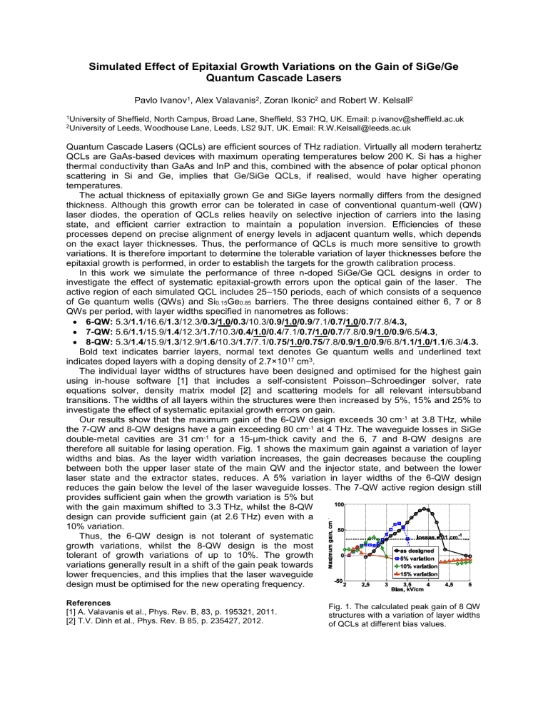
Our results show that the maximum gain of the 6-QW design exceeds 30 cm -1 at 3.8 THz, while the 7-QW and 8-QW designs have a gain exceeding 80 cm -1 at 4 THz. The waveguide losses in SiGe double-metal cavities are 31 cm -1 for a 15μm-thick cavity and the 6, 7 and 8-QW designs are therefore all suitable for lasing operation. Fig. 1 shows the maximum gain against a variation of layer widths and bias. As the layer width variation increases, the gain decreases because the coupling between both the upper laser state of the main QW and the injector state, and between the lower laser state and the extractor states, reduces. A 5% variation in layer widths of the 6-QW design reduces the gain below the level of the laser waveguide losses. The 7-QW active region design still provides sufficient gain when the growth variation is 5% but with the gain maximum shifted to 3.3 THz, whilst the 8-QW design can provide sufficient gain (at 2.6 THz) even with a
10% variation.
Thus, the 6-QW design is not tolerant of systematic growth variations, whilst the 8-QW design is the most tolerant of growth variations of up to 10%. The growth variations generally result in a shift of the gain peak towards lower frequencies, and this implies that the laser waveguide design must be optimised for the new operating frequency.
References
[1] A. Valavanis et al., Phys. Rev. B, 83, p. 195321, 2011.
[2] T.V. Dinh et al., Phys. Rev. B 85, p. 235427, 2012.
Fig. 1. The calculated peak gain of 8 QW structures with a variation of layer widths of QCLs at different bias values.


