Laboratory work 9 The study of bipolar transistor Theoretical
advertisement
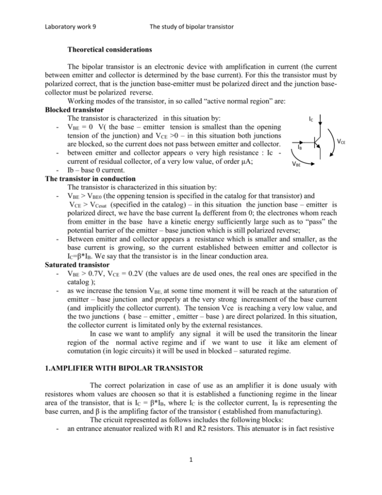
Laboratory work 9 The study of bipolar transistor Theoretical considerations The bipolar transistor is an electronic device with amplification in current (the current between emitter and collector is determined by the base current). For this the transistor must by polarized correct, that is the junction base-emitter must be polarized direct and the junction basecollector must be polarized reverse. Working modes of the transistor, in so called “active normal region” are: Blocked transistor The transistor is characterized in this situation by: IC - VBE = 0 V( the base – emitter tension is smallest than the opening tension of the junction) and VCE >0 – in this situation both junctions VCE are blocked, so the current does not pass between emitter and collector. IB - between emitter and collector appears o very high resistance : Ic current of residual collector, of a very low value, of order μA; VBE - Ib – base 0 current. The transistor in conduction The transistor is characterized in this situation by: - VBE > VBE0 (the oppening tension is specified in the catalog for that transistor) and VCE > VCesat (specified in the catalog) – in this situation the junction base – emitter is polarized direct, we have the base current IB defferent from 0; the electrones whom reach from emitter in the base have a kinetic energy sufficiently large such as to “pass” the potential barrier of the emitter – base junction which is still polarized reverse; - Between emitter and collector appears a resistance which is smaller and smaller, as the base current is growing, so the current established between emitter and collector is IC=β*IB. We say that the transistor is in the linear conduction area. Saturated transistor - VBE > 0.7V, VCE = 0.2V (the values are de used ones, the real ones are specified in the catalog ); - as we increase the tension VBE, at some time moment it will be reach at the saturation of emitter – base junction and properly at the very strong increasment of the base current (and implicitly the collector current). The tension Vce is reaching a very low value, and the two junctions ( base – emitter , emitter – base ) are direct polarized. In this situation, the collector current is limitated only by the external resistances. In case we want to amplify any signal it will be used the transitorin the linear region of the normal active regime and if we want to use it like am element of comutation (in logic circuits) it will be used in blocked – saturated regime. 1.AMPLIFIER WITH BIPOLAR TRANSISTOR The correct polarization in case of use as an amplifier it is done usualy with resistores whom values are choosen so that it is established a functioning regime in the linear area of the transistor, that is IC = β*IB, where IC is the collector current, IB is representing the base curren, and β is the amplifing factor of the transistor ( established from manufacturing). The cricuit represented as follows includes the following blocks: - an entrance atenuator realized with R1 and R2 resistors. This atenuator is in fact resistive 1 Laboratory work 9 The study of bipolar transistor frequency divider introduced only because the signal sources in the laboratory do not allow to generate signals of low amplitude (untill 1V). - decouple capacitor C1 - allows the elimination of the continuos components of the input signal. This way is ensured only the amplification of the alternative component of the input signal ( the useful component of the signal) this way the amplifier could enter in limitation. You observe that “ static operating point” it refers to the fact that in the absence of input signal, the transistor is opened, this is determined by direct measurement in the circuit of voltage drops. Powering + 5Vcc pct 1 pct 2 RB1 RB1 100K 100K pct 3 C2 OUT C1 330n R1 100K R2 ~ 1K 330n RB2 100K Electric scheme of amplifier 2.INVERTER WITH BIPOLAR TRANSISTOR It is observed, in case of this circuit, the lack of any capacitors. This requires a much faster operating regime, at the expense of consumed power and the risk of destruction of components. Powering + 5Vcc pct 1 pct 2 RC 100K R1 100K ~ R2 1K Electric scheme of inverter 2 pct 3 OUT Laboratory work 9 The study of bipolar transistor In this case we do not need the polarization circuit of the base because the transistor is used in “all or nothing” regime – blocked or saturated. The input circuit, realized with RB1 and RB2, is realizing a frequency divider, taking into consideration that the logical circuits are tension levels for “1” logic over 2V, which is dangerous to base-emitter junction. If VIN has the value 0V, compatible to 0 logic level , the transistor is blocked and the tension VOUT will have the maximum value, compatible to 1 logic level. If V IN has the value 5V, compatible to 1 logic level, the transistor Q1 is opened and the tension VOUT will have the value of about 0.2V, compatible to 0 logic level. STEPS TO FOLLOW The study amplifier 1. we power the stabilized supply and from the control potentiometer we adjust the value of 5V. 2. with the multimeter we measure the terminal voltage source and then the supply stops; 3. it is connected the stabilized supply at the powering wires ( marked +5V and ground), taking into account the polarity ( ground of supply to ground of the circuit); 4. powering the power supply and with the multimeter measure the voltages across the junctions ( base potential, emitter and collector in relation with the ground). Note these outages and determine the transistor state; 5. the oscilloscope probe is connected to the signal generator (attention: not at the stabilized power supply !!!!); 6. the source is powered and adjust it (watching the oscilloscope screen) to generate: - sinusoidal signal; - frequency of 5kHz - amplitude of 2V peak to peak - 1V continuous component 7. connect the generator round to the montage ground and the + terminal is connected to the input of the test circuit; 8. move probe 1 of the oscilloscope in test point 1 and probe 2 it input in test point 2. Note the amplitude difference between the signal applied at the input and that after the resistive divider! 9. Move probe 1 of the oscilloscope in test point 2 and probe 2 in test point 3 ( output of the amplifier) 10. determine the amplification of the circuit, by comparing the output amplitude signal to signal amplitude in test point 2. 11. increase the amplitude of the signal provided by generator. Up to what value of the test point 2 the output signal is correct amplified? Note the value! 12. return to the amplitude of generated signal of 2V and change of the generated signal ; 13. note the minimum frequency and the maximum frequency at which the amplification circuit is working properly. 3 Laboratory work 9 The study of bipolar transistor Study of the inverter 1. set the output voltage of the stabilized supply at a value of 5V; 2. power the assembly; 3. source signal is passed in working mode "TTL" and moves the probe to that output 4. the generator is connected to input of the circuit.View the waveforms in test points. Determine the maximum operating frequency of the circuit! 4

