Measuring the velocity of light
TEP
2.1.01
-01
Related Topics
Refractive index, wavelength, frequency, phase, modulation, heterodyne technique, electric field constant, magnetic field constant.
Principle
The intensity of a laser diode is modulated with a high frequency and the beam is reflected, after travelling some distance, back into the apparatus. The phase of the received signal is compared to the one
transmitted. The velocity of light is then calculated from the measured phase difference, the modulation
frequency and the length of the light path.
Equipment
1 Speed of Light meter (complete set)
2 Screened cable, BNC, l = 750 mm
1 Digital Oscilloscope 25 MHz, 2 channels
11226-88
07542-11
11456-99
Tasks
1. Determine the velocity of light in air.
2. Determine the velocity of light in water and calculate the refractive index.
3. Determine the velocity of light in acrylic glass and calculate the refractive index.
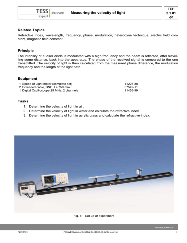
Fig. 1: Set-up of experiment
www.phywe.com
P2210101
PHYWE Systeme GmbH & Co. KG © All rights reserved
1
TEP
2.1.01
-01
Measuring the velocity of light
Set-up and Procedure
The light velocity measuring apparatus and the mirror are set up in such a way that the laser beam hits
the mirror no matter where along the base the mirror
is placed (more detailed directions can be found in
the operating instructions of the Speed of Light meter). First the socket femmit/1000 is connected to the
oscilloscope and the modulation frequency femmit (divided by 1000) is determined. The reason for introducing the fixed factor 1/1000 into the hardware between the modulator and the socket, is that a relatively simple oscilloscope can be used for the task.
After determination of the modulation frequency, the
two other sockets (femmit – fsync and frec – fsync) are
connected to the two input sockets of the oscilloscope. The frequencies of the emitted and the received signal are also reduced to 50 KHz while conserving their phase relation so that they can be disFig. 2. Oscilloscope signal after “Calibration”.
played on this type of oscilloscope.
Task 1: The velocity of light in air
At the start the mirror is placed close to the operating unit, the mode “Δφ” is selected and the button
“Calibration” is pressed to have two coinciding signals visible on the oscilloscope. (See Fig. 2)
The mirror is then slid along the graduated scale.
For at least 10 different displacements Δx (> 100
cm) the time difference Δt is calculated from the
readings performed on the oscilloscope. (See Fig.
3).
Task 2: The Velocity of light in water and Task 3:
The Velocity of light in acrylic glass
The water-filled tube or the acrylic glass rod is
placed so that the laser beam runs through them, Fig. 3. Measuring the time difference using the oscillothe mirror is placed directly behind. The “Calibration” scope.
button is pressed. Again the oscilloscope will show a
graph similar to Fig. 2. The tube/rod is then taken
out of the path of the rays, the two signals will not coincide any longer. Now the mirror is moved a distance Δx until the two signals on the oscilloscope coincide again as before with the medium inserted. The
mirror displacement Δx is measured several times.
2
PHYWE Systeme GmbH & Co. KG © All rights reserved
P2210101
TEP
2.1.01
-01
Measuring the velocity of light
Theory and evaluation
Although light travels very fast, its velocity is finite. Since 1676 when Romer estimated the velocity of light using spatial scales that included
the distances to the moons of Jupiter much
technical development took place. These days
we can comfortably measure the speed of light
on a table top. In the SI system, the metre is defined as the di tance light travels in vacuum in
1/299792458 of a second. The effect of this definition is to fix the speed of light in vacuum at
exactly
299 792 458 m/s.
Velocity of light in air:
To obtain the velocity of light, one has calculate
Δt/Δs. Where Δt is the time the light takes to
travel the distance Δs. The distance Δs is 2·Δx
because the additional stretch is twice the mirror
displacement since the laser beam has to travel
to the mirror and back again.
Table 1 gives an example of a measurement:
c = Δs/Δt
Δx in mm
Δs in mm
Δt in ns
1000
2000
6.6
3.03
1100
2200
7.3
3.01
1200
2400
7.9
3.03
1300
2600
8.6
3.02
1350
2700
9.0
3.00
1400
2800
9.3
3.01
1450
2900
9.6
3.02
1500
3000
9.9
3.03
1550
3100
10.3
3.01
1600
3200
10.6
3.02
in (m/s ·108)
av. val.: 3.018
Velocity of light in water/acrylic glass
The velocity of light in water or acrylic glass, cm,
is measured by comparing it with the velocity of
light in air ca (Fig. 4). In the first measurement (with the medium), the light travels a distance l1 in time t1
(l1 = 2x1).
In the second measurement (no medium), the light travels a distance l2 = l1 + 2Δx in the same time. This
Fig. 4: Principle for measuring the velocity of light in a medium
www.phywe.com
P2210101
PHYWE Systeme GmbH & Co. KG © All rights reserved
3
TEP
2.1.01
-01
Measuring the velocity of light
means that light takes the same time to travel the distance 2Δx + 2lm in air as it takes to travel the distance 2lm in the medium.
From this and the definition of the refractive index, it follows directly, that
𝑛𝑚 =
(2∆𝑥 + 2𝑙𝑚 ) (∆𝑥 + 𝑙𝑚 )
=
2𝑙𝑚
𝑙𝑚
𝑐𝑚 =
𝑐𝑎
𝑛𝑚
and
For the water-filled tube, with lm= 500 mm as the length of the water column and a measured Δx of 170
mm, this leads to:
n = 1.34, (literature value: nwater = 1.33)
cwater = 2.23 · 108 m/s
For the acrylic glass cylinder, with lm= 490 mm and Δx = 240 mm:
n = 1.49, (literature values are in the range from: n = 1.48 to n = 1.52)
cacrylic glass = 2.01 · 108 m/s
Note
The evaluation as described here relies completely on the measurements performed with the oscilloscope. No use is made of the displayed values on the velocity of light apparatus.
The reasons for this are mainly didactical ones: The students learn to operate an oscilloscope and they
will trust the results more if they measured them themselves this way instead of taking the reading off an
apparatus that is made just for this specific measurement. Nevertheless, in many settings (e.g. demonstration in class) it might be quite helpful to use the features built into the apparatus that are described in
the manual.
4
PHYWE Systeme GmbH & Co. KG © All rights reserved
P2210101


