Wave Energy.pdf
© 2003 Taylor & Francis Books, Inc.
Exploiting the low, variable frequency motion of waves, and coupling the power to a fixed frequency
and fixed voltage grid system, is a challenging task which device designers have tackled in different
ways.
Conversion principles
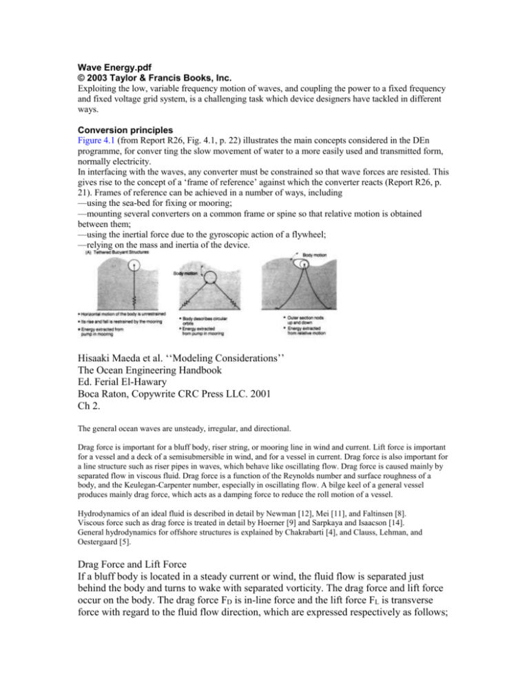
Figure 4.1 (from Report R26, Fig. 4.1, p. 22) illustrates the main concepts considered in the DEn
programme, for conver ting the slow movement of water to a more easily used and transmitted form,
normally electricity.
In interfacing with the waves, any converter must be constrained so that wave forces are resisted. This
gives rise to the concept of a ‘frame of reference’ against which the converter reacts (Report R26, p.
21). Frames of reference can be achieved in a number of ways, including
—using the sea-bed for fixing or mooring;
—mounting several converters on a common frame or spine so that relative motion is obtained
between them;
—using the inertial force due to the gyroscopic action of a flywheel;
—relying on the mass and inertia of the device.
Hisaaki Maeda et al. ‘‘Modeling Considerations’’
The Ocean Engineering Handbook
Ed. Ferial El-Hawary
Boca Raton, Copywrite CRC Press LLC. 2001
Ch 2.
The general ocean waves are unsteady, irregular, and directional.
Drag force is important for a bluff body, riser string, or mooring line in wind and current. Lift force is important
for a vessel and a deck of a semisubmersible in wind, and for a vessel in current. Drag force is also important for
a line structure such as riser pipes in waves, which behave like oscillating flow. Drag force is caused mainly by
separated flow in viscous fluid. Drag force is a function of the Reynolds number and surface roughness of a
body, and the Keulegan-Carpenter number, especially in oscillating flow. A bilge keel of a general vessel
produces mainly drag force, which acts as a damping force to reduce the roll motion of a vessel.
Hydrodynamics of an ideal fluid is described in detail by Newman [12], Mei [11], and Faltinsen [8].
Viscous force such as drag force is treated in detail by Hoerner [9] and Sarpkaya and Isaacson [14].
General hydrodynamics for offshore structures is explained by Chakrabarti [4], and Clauss, Lehman, and
Oestergaard [5].
Drag Force and Lift Force
If a bluff body is located in a steady current or wind, the fluid flow is separated just
behind the body and turns to wake with separated vorticity. The drag force and lift force
occur on the body. The drag force FD is in-line force and the lift force FL is transverse
force with regard to the fluid flow direction, which are expressed respectively as follows;
where ρ is the fluid density, the drag coefficient CD and lift coefficient CL are the
function of configuration of a structure, SA is the projected area of a structure, and V is
the relative velocity of a fluid. Strictly speaking, the coefficients CD and CL are dependent
on the Reynolds number, however, in full-scale case, the Reynolds number is relatively
high in turbulence range and the CD, CL are almost functions of the configuration of a
structure. The practical value for CD is as follows; CD 1.17 for a 2D circular cylinder,
2.05 for a 2D rectangular cylinder, 0.5 for a 3D sphere, and 1.05 for a 3D cube. For more
details on CD, CL, see Hoerner [9].
decreases. As the wave drift coefficient FDX decreases, the structure rigidity becomes
more flexible as
shown in Fig. 2.17.
Dynamics of Underwater Vehicles and FPSO (A Single Point Moored Vessel)
Two coordinate systems are used to analyze dynamics of underwater vehicles or FPSO
including the spacefixed coordinate system and the body-fixed coordinate system. The
location of the vessel is expressed in the space-fixed coordinate system, while the motion
dynamics of the vessel in current and waves is formulated in the so-called maneuvering
equation of a ship. The general maneuvering equation in 3D is written as
follows;
where V = {u, v, w} and = {p, q, r} are velocity of a body and angular velocity on the
body-fixed coordinate system, respectively. V ˙= dV_/ dt and so on.
where “m” is mass of a body, “Iik” is general moment of inertia, “F,” “” are external
force and moment, respectively, “h” is the angular momentum vector, and [] is
generalized added mass. “F” and “” consist of wave excitation, wave making damping,
viscous force, tension due to mooring line, hydrostatic force, and so on.
Once Eq. (2.46) is solved, the vector “V,” “” is obtained and then the location of the
body in space can be derived through the transformation of the body-fixed coordinate and
the space-fixed coordinate using the Eulerian angle as follows:
The above equations hold in 3D and are applicable to the motion of underwater vehicles,
while in the horizontal plane motion, only “u, v, r,” which are x-direction velocity, ydirection velocity, and angular velocity around the z-axis, are the key parameters.
Coastal Engineering
journal homepage: www.elsevier.com/ locate/coastaleng
The effect of relative crest submergence on wave breaking over submerged
slopes
C.E. Blenkinsopp 1, J.R. Chaplin ⁎
School of Civil Engineering and the Environment, University of Southampton, Highfield, Southampton SO17 1BJ, UK
© 2008 Elsevier B.V. All rights reserved
3.1.1. Breaker depth index
The breaker depth index γb is used to determine the break point in nearshore wave models and is important
for the calculation of forces on coastal structures in shallow areas. The index is defined as
b = Hb / hb
where Hb and hb are the wave height and water depth at the break point respectively, as shown in Fig
3.1.2. Breaker height index
The breaker height index is defined as
b = Hb / H0
3.2.1. Energy dissipation – why we need to capture energy before the wave breaks
Wave breaking is associated with the generation of high levels of turbulence, air entrainment, noise and splash, all of which must
contribute to the energy dissipation and which are seen to increase with wave breaking intensity as waves become more plunging in
nature.
a relationship between breaking intensity and initial energy dissipation, showing that the total energy dissipated in the breaking event
for each wave case increases as the relative cavity area becomes larger, i.e. as the intensity of breaking increases.
Status of Wave and Tidal Power
Technologies for the United States
W. Musial
Technical Report
NREL/TP-500-43240
August 2008
Marine Renewable Energy Resource Estimates
Wave Resource: Generally, wave energy increases with latitude and has greater potential on
the west coast of the United States because global winds tend to move west to east across the
Pacific Ocean. The total energy contained in the waves is dependent on the linear length of
wave crest, the wave height and the wave period. Wave energy resource assessments have
been performed by the Electric Power Research Institute (EPRI) and the methods for
calculation are well documented [3,4,5,6,7,8]. Coastal areas with wave resources below 10kW/m were not included in the estimates.
Table 1 shows the gross wave energy resource by region. This is an estimate of the energy
contained in the incident waves if it were converted to electricity.
Table 1 – Wave Resource by Region
US Wave Resource Regions (>10kW/m)
TWh/yr
New England and Mid-Atlantic States
100
Northern California, Oregon and Washington
440
Alaska (exclusive of waves from the Bering Sea)
1,250
Hawaii and Midway Islands
330
Marine energy devices are generally classified first by their resource type and next by their
method of energy capture. The wave devices that have been demonstrated so far are
subdivided into several categories including, point absorbers, attenuators, and two kinds of
terminators; overtopping and oscillating water column. Point absorbers and attenuators are
installed in the wave field and extract a portion of energy from waves that pass through.
Terminators stop the wave, absorbing most of the wave’s energy. A small fraction of the
energy is reflected back to sea. Because the different types of devices are described in various
references [16, 17, 4], only brief descriptions are provided below.
A point absorber typically comprises a buoyant float that heaves up and down with waves
relative to a moored component that is stationary in the heave direction (see Figure 1).
Energy generation is associated with this relative motion through a conversion device.
Conversion devices can be various forms of linear electric generators, or hoses and pumps
that create high fluid pressure to be converted later in a central generating station.
Energy Policy
journal homepage: www.elsevier.com/locate/enpol
Enabling science and technology for marine renewable energy by MarkusMueller
and RobinWallace Institute for Energy Systems,
JointResearchInstituteforEnergy,UKEnergyResearchCentre,SchoolofEngineeringandElectronics,Universityof
Edinburgh, The King’sBuildings,EdinburghEH93JL,UK
Available online 25 October 2008
The motion and response of a wave energy device may be described in terms of impedances with magnitude and phase that are
subjected to excitation by composite and varying frequencies. The ratio of force to velocity defines a damping coefficient at each
frequency. The force:displacement ratio at low frequency suggests a hydrostatic spring constant. The force:body acceleration ratio
defines a total inertia. Force and velocity vary cyclically but may be out of phase because of the reactive components of inertia and
stiffness. The frequency at which force is exactly in phase with velocity is the point of resonance and maximum energy conver- sion.
Ideally, the damping coefficient should be adjustable across the spectrum of wave action to optimise response, and a complexconjugate control system should be able to cancel the reactive terms at all frequencies. The sea is non-stationary and the centre
frequency can vary continuously. Either the response of the device has to be continually retuned for maximum energy capture, or the
device response has to be flatter over a range of frequencies.


