Document 5901838
advertisement
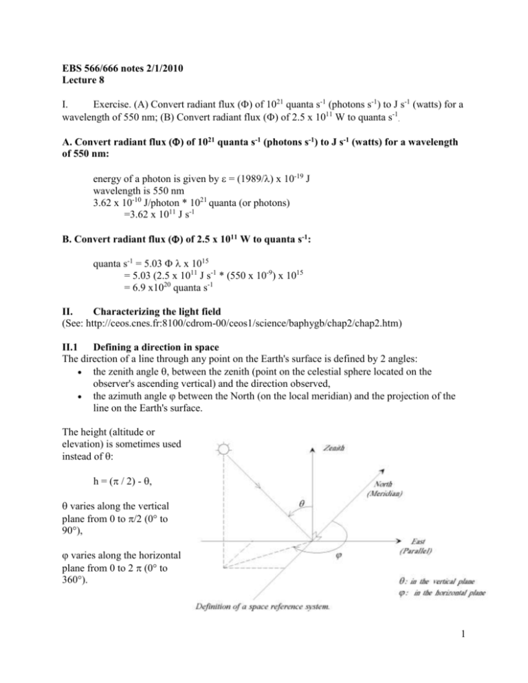
EBS 566/666 notes 2/1/2010 Lecture 8 I. Exercise. (A) Convert radiant flux () of 1021 quanta s-1 (photons s-1) to J s-1 (watts) for a wavelength of 550 nm; (B) Convert radiant flux () of 2.5 x 10¹¹ W to quanta s-1. A. Convert radiant flux () of 1021 quanta s-1 (photons s-1) to J s-1 (watts) for a wavelength of 550 nm: energy of a photon is given by = (1989/) x 10-19 J wavelength is 550 nm 3.62 x 10⁻¹⁰ J/photon * 1021 quanta (or photons) =3.62 x 10¹¹ J s-1 B. Convert radiant flux () of 2.5 x 10¹¹ W to quanta s-1: quanta s-1 = 5.03 x 1015 = 5.03 (2.5 x 10¹¹ J s-1 * (550 x 10-9) x 1015 = 6.9 x10²⁰ quanta s-1 II. Characterizing the light field (See: http://ceos.cnes.fr:8100/cdrom-00/ceos1/science/baphygb/chap2/chap2.htm) II.1 Defining a direction in space The direction of a line through any point on the Earth's surface is defined by 2 angles: the zenith angle , between the zenith (point on the celestial sphere located on the observer's ascending vertical) and the direction observed, the azimuth angle between the North (on the local meridian) and the projection of the line on the Earth's surface. The height (altitude or elevation) is sometimes used instead of : h = ( / 2) - , varies along the vertical plane from 0 to /2 (0° to 90°), varies along the horizontal plane from 0 to 2 (0° to 360°). 1 II.2 Definitions II.2.1 Solid Angle: a solid angle ddelimits a cone in space: d = dS / r2 (in Steradians, Sr) where dS is the area cut by the cone over a sphere of radius r, the center of which is at the apex of the cone. II.2.2 Intensity: intensity is the power emitted by a point source A per solid angle unit. IA = dW/d (in W.Sr-1) If the intensity is the same in all directions, the source is called isotropic. Whenever a source does not have the same power in all directions it is said to be anisotropic. This notion is rarely used in remote sensing, as the Earth's surface observed by satellite is not a point source. II.2.3 Radiance: radiance (L) is the power emitted (dW) per unit of the solid angle (d) and per unit of the projected surface (ds cos) of an extended widespread source in a given direction (). L = d2W / (d. ds. cos) (in W.Sr-1. m-2) 2 II.2.4 Irradiance: power received per surface unit from all directions (hemispheric, 2 halves). E = dW / dS (in Wm-2) The element of the Earth's surface ds receives an irradiance E from the upper half space and acts for the sensor as a source of radiance L along a direction . II.3 Light in water Velocity of light in a medium = velocity of light in a vacuum divided by the refractive index of the medium (refractive index of water is 1.33) Frequency of radiation is the same in water and in a vacuum, but the wavelength diminishes in proportion to the decrease in velocity in water vs. a vacuum; c and change in parallel. Given= c/wheredoes not vary, must decrease. III. Inherent Optical Properties (IOP): IOPs are properties that depend only on the water and other substances that are dissolved or suspended in it, as distinguished from Apparent Optical Properties (AOPs). The two fundamental IOPs are absorption (a) and the Volume Scattering Function (ß). Others commonly derived from these include the total scattering coefficient (b), backscattering coefficient (bb), and beam attenuation coefficient (c = a + b). III.1 Absorption (a): The absorption coefficient is the fraction of incident power that is absorbed within an infinitesimal volume, divided by the distance of propagation through the volume, expressed in m-1. III.2 Volume Scattering Function (): The Volume Scattering Function, or VSF, notated mathematically as ß ("beta") characterizes the intensity of scattering as a function of angle. The VSF is defined in terms of a beam of light incident on an infinitesimal volume. At each angle 3 from 0° (the original angle of the incident light) to 180°, the VSF is the ratio of the intensity of scattered light (in W/sr) to the incident irradiance (in W/m2), per unit volume (in m3). Therefore the VSF's units are (W/sr) / (W/m2 m3) = sr-1 m-1. III.3 Scattering Coefficient (b): Also called the Total Scattering Coefficient: the fraction of a collimated beam, incident on an infinitesimal volume, that is scattered (in all directions) per meter of distance. The total scattering coefficient b is calculated by integrating ß over all angles, and is also equal to the integral of the Volume Scattering Function over all angles. III.4 Backscattering Coefficient (bb): The backscattering, or backward scattering, coefficient, in units of m-1. It indicates the attenuation caused by scattering at angles from 90° to 180°. bb is commonly estimated from measurements of the VSF around a single fixed angle. bf is the forward-scattering equivalent of bb, indicating scattering in the range of 0° to 90°. Discussions of scattering often refer to the Scattering Phase Function, which is equal to ß/b. Because b is the integral of ß with respect to angle, the integral of the phase function with respect to angle is 1. III.5 Attenuation Coefficient, Beam (c): The attenuation experienced by a hypothetical perfectly collimated beam of light. Represented as c, it is equal to a (absorption coefficient) + b (scattering coefficient). It is measured by a transmissometer, which ideally receives only the unscattered light that traverses the path from its source to its receiver. Because every practical transmissometer has imperfect beam collimation and a finite field of view, some scattered light is collected by the receiver, causing c to be underestimated. For example, HOBI Labs' c-ßeta has divergence and FOV of less than 0.5° (half-angle), resulting in c values that are slightly higher (and more accurate) than other transmissometers with wider divergence angles. IV. Apparent Optical Properties (AOPs): Properties that depend both on inherent optical properties (IOPs) and on the light field in which they are measured. The most widely-used AOP is the diffuse attenuation coefficient Kd. Kd is essentially the attenuation experienced by sunlight, and its value depends on depth, sun angle, sky conditions, and shadowing by objects on the surface. However as depth increases, the influence of the surface illumination characteristics decreases, and Kd eventually reaches an asymptotic value that is in fact an IOP. Thus the distinction between IOPs and AOPs can sometimes be misleading. In practice, every optical measurement is dependent on the light field used for the measurement, but instruments for IOP measurements provide their own controlled light field rather than relying on ambient light. In contrast, AOPs are typically derived from measurements of ambient light. 4


