Geometric transformations Date: 07/26/04
advertisement
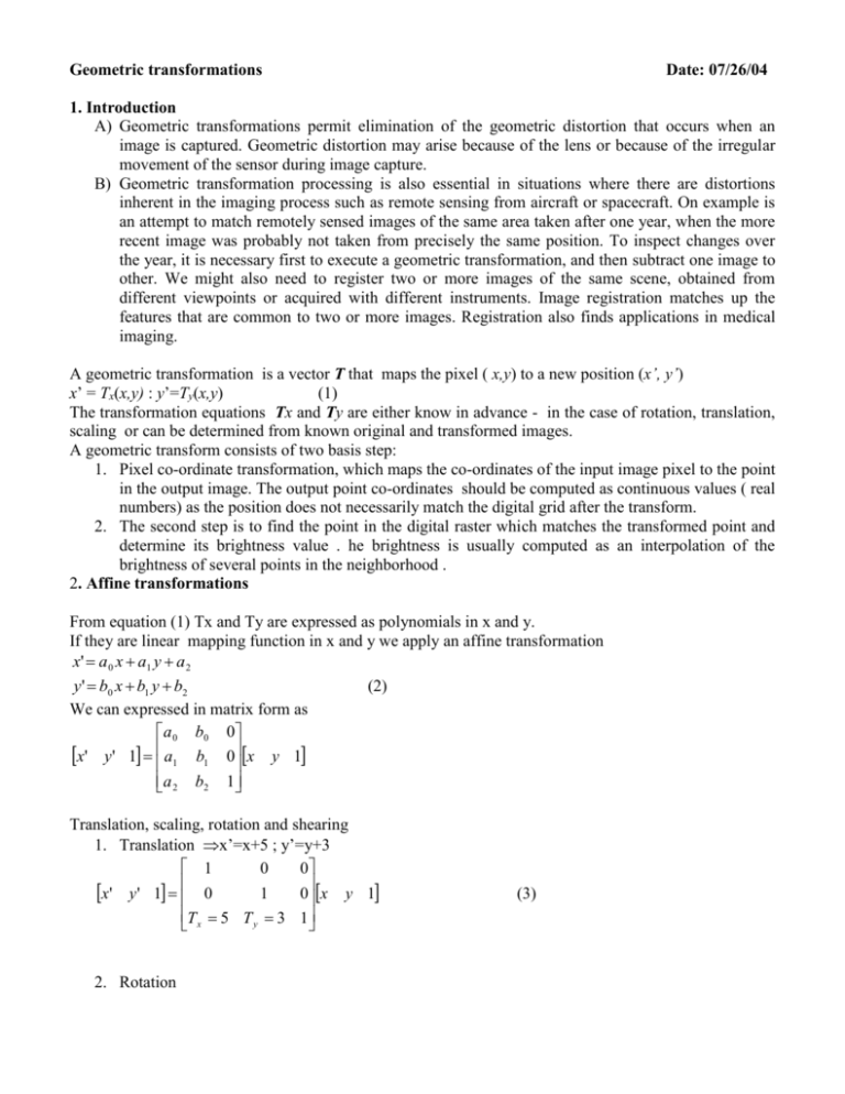
Geometric transformations Date: 07/26/04 1. Introduction A) Geometric transformations permit elimination of the geometric distortion that occurs when an image is captured. Geometric distortion may arise because of the lens or because of the irregular movement of the sensor during image capture. B) Geometric transformation processing is also essential in situations where there are distortions inherent in the imaging process such as remote sensing from aircraft or spacecraft. On example is an attempt to match remotely sensed images of the same area taken after one year, when the more recent image was probably not taken from precisely the same position. To inspect changes over the year, it is necessary first to execute a geometric transformation, and then subtract one image to other. We might also need to register two or more images of the same scene, obtained from different viewpoints or acquired with different instruments. Image registration matches up the features that are common to two or more images. Registration also finds applications in medical imaging. A geometric transformation is a vector T that maps the pixel ( x,y) to a new position (x’, y’) x’ = Tx(x,y) : y’=Ty(x,y) (1) The transformation equations Tx and Ty are either know in advance - in the case of rotation, translation, scaling or can be determined from known original and transformed images. A geometric transform consists of two basis step: 1. Pixel co-ordinate transformation, which maps the co-ordinates of the input image pixel to the point in the output image. The output point co-ordinates should be computed as continuous values ( real numbers) as the position does not necessarily match the digital grid after the transform. 2. The second step is to find the point in the digital raster which matches the transformed point and determine its brightness value . he brightness is usually computed as an interpolation of the brightness of several points in the neighborhood . 2. Affine transformations From equation (1) Tx and Ty are expressed as polynomials in x and y. If they are linear mapping function in x and y we apply an affine transformation x' a 0 x a1 y a 2 y' b0 x b1 y b2 (2) We can expressed in matrix form as a 0 b0 0 x' y' 1 a1 b1 0x y 1 a 2 b2 1 Translation, scaling, rotation and shearing 1. Translation x’=x+5 ; y’=y+3 1 0 0 x' y' 1 0 1 0x y 1 T x 5 T y 3 1 2. Rotation (3) cos x' y' 1 sin 0 sin cos 0 0 0x 1 y 1 (4) 3. Scaling S x x' y' 1 0 0 0 Sy 0 0 0x 1 y 1 (5) 4. Shear Now we consider the case where a0= b1=1 and b0=0 By allowing a1 to be nonzero , x’ is made linearly dependent on both x and y’, while y remains identical to y. The shear transform along the x-axis is 1 0 0 (6) x' y' 1 Sy 1 0x y 1 0 0 1 Similar, the shear transform along the y-axis is 1 Sx 0 x' y' 1 0 1 0x y 1 0 0 1 (7) 5. Composite Transformation [x’ y’ 1] =Mcomp [x y 1] where 1 0 0 cos Mcomp 0 1 0 sin Tx Ty 1 0 sin cos 0 0 Sx 0 0 0 Sy 0 1 0 0 1 (8) 6. Inverse T-1 =(adjoint T)/(determinant T) The adjoint of matrix is simply the transpose of the matrix of cofactors. b1 a 0 b 0 0 1 x y 1 x' y' 1 a1 b1 0 x y 1 a1 a 0 b1 a1b0 a 2 b2 1 a1b2 a 2 b1 7. Defining coefficients for Affine Transformation x 0 ' y 0 ' 1 x 0 y 0 1 a 0 b0 0 x ' y ' 1 x 1 1 1 y1 1 a1 b1 0 x 2 ' y ' 2 1 new x 2 y 2 1 a 2 b2 1 b0 a0 a 2 b0 a 0 b2 (9) 0 a 0 b1 a1b0 0 X’=XA A=X-1 Xnew’ a 0 a 1 a 2 b0 b1 b2 0 y 2 y0 y 0 y1 x 0 ' y 0 ' 1 y1 y 2 1 0 x2 x1 x0 x 2 x1 x0 x1 ' y1 ' 1 (10) det( X ) x1y 2 x2 y1 x2 y 0 x0 y 2 x2 y1 x1y 0 x 2 ' y ' 2 1 new 1 det(X) = x0(y1-y2)-y0(x1-x2)+(x1y2-x2y1) (x’0,y’0) (x0,y0) (x1,y1) (x’1,y’1) (x2,y2) Input image (x’2,y’2) Output image 3. Geometric transformation algorithms 3.1 Forward mapping Let us consider that you want to apply rotation to two different pixels 1) the pixel at (0,100) after a 90 rotation 2) the pixel at (50,0) after a 35 rotation cos sin 0 x' y' 1 sin cos 0x y 1 0 0 1 cos90=0, sin90=1 (-100,0) x’=xcos -ysin = 50cos(35)=40.96 y’=xsin+ycos = 50sin(35)=28.68 Problems : 1. Input pixel may map to apposition outside the screen . This problem can be solved by testing coordinates to check that they lie within the bounds of the output image before attempting to copy pixel value. 2. Input pixel may map to a non-integer position . Simple solution is to find the nearest integers to x’ and y’ and use these integers as a coordinates of the transformed pixel. 3.2 Inverse Mapping 4. Interpolations schemes Interpolation is the process of determining the values of a function at positions lying between its samples. It achieves this process by fitting a continuous function through the discrete input samples. Interpolation reconstructs the signal lost in the sampling process by smoothing the data samples with a interpolation function. It woks as a low-pass filter. For equally spaced data, interpolation can be expressed by K 1 f ( x ) c k h( x x k ) (11) k 0 where h is interpolation kernel weighted by coefficients ck and applied to K data samples , xk. Equation (11) formulates interpolation as a convolution operation. In practice , h is nearly always a symmetric kernel h(-x) =h(x). Furthermore, we will consider the ck coefficients are the data samples themselves. If x is offset from the nearest point by distance d , where 0 d <1, we sample the symmetric kernel at h(d) and h(1+d). Commonly use finite impulse response filters ( FIR ) include the box, triangle, cubic, cubic B-spline convolution kernel. f(xk) h(x) x xk Resampled Point x Interpolation Function x 4.1 Zero-order interpolation The rounding of calculated coordinates (x’,y’) to there nearest integers is a strategy known as zero-order ( or nearest-neighbour ) interpolation. Each interpolated output pixel is assigned the value of the nearest sample point in the input image . This technique, also known as the point shift algoritrhm is given by the following interpolation polynomial: x k 1 x k x x k 1 (12) f ( x) f ( x k ) x k 2 2 It can be achieved by convolving the image with a one-pixel width rectangle in the spatial domain. The interpolation kernel for the nearest neighbor algorithm is defined as 1 0 x 0.5 h( x ) 0.5 x 0 4.2 Linear Interpolation Given an interval (x0,x1) and function values f0 and f1 for the endpoints, the interpolating polynomial is (13) f ( x) a1 x a 0 where a0 and a1 are determined by solving x x f 0 f 1 a1 a 0 0 1 1 1 This give rise to the following interpolating polynomial x x0 f 1 f 0 f ( x) f 0 x x 0 1 This is equation of a line joining points (x0,f0) and (x1,f1). In the spatial domain, linear interpolation is equivalent to convolving the sampled input with the following interpolation kernel: 1 x 0 x 1 h( x ) triangle filter 0 1 x 4.3 Bilinear interpolation ( First –order interpolation) Let f(x,y) be a function of two variables that is known at the vertices of the unit square. Suppose we desire to establish by interpolation the value of f(x,y) at an arbitrary point inside the square. We can do so by fitting a hyperbolic paraboloid, defined by the bilinear equation f(x,y)=ax + by +cxy +d through the four known values (14) The four coefficients a through d are to be chosen so that f(x,y) fits the known values at the four corners. First, we linearly interpolate between the upper two points to establish the value of f(x,0) = f(0,0) + x[f(1,0)-f(0,0) (15) Similarly for two lower points, f(x,1)=f(0,1) + x[f(1,1)-f(0,1)] (16) f(x,y)=f(x,0)+y[f(x,1)-f(x,0)] From (15), (16 ) and (17) we receive (17) f(x,y) =[f(1,0) – f(0,0)]x +[f(0,1)-f(0,0)]y + [f(1,1)+f(0,0)-f(0,1)-f(1,0)]xy +f(0,0) (18) which is in the form of Eq. 14 and is thus bilinear. f(1,0) f(1,1) f(x,y) f(0,0) 1,0 x,0 x, y 0,0 0,y 1,1 f(0,1) 0,1 y Bilinear transformation X’ = a0xy + a1x + a2y + a3 Y’ = b0xy +b1y +b2y + b3 (19) Bilinear mapping preserve lines that are horizontal or vertical in the source image. Thus, points along horizontal and vertical lines in the source image( including borders) remain equispaced. However, lines not oriented along these two directions (e.g. diagonal) are not preserved as lines. Instead, diagonal lines map onto quadratic curves at the output image. Bilinear mappings are defined through piecewise functions that must interpolate the coordinate assignments specified at the vertices. This scheme is based on bilinear interpolation to evaluate the X and Y mapping functions. 5. Polynomial Transformation Geometric correction requires a spatial transformation to invert an unknown distortion function. The mapping functions, U and V , have been universally chosen to be global bivariate polynomial transformations of the form: N N i u a ij x i y j i 0 j 0 N N 1 v bij x i y j (20) i 0 j 0 where aij and bij are constant polynomial coefficients A first degree ( N=1) bivariate polynomial defines those mapping functions that are exactly given by a general 3 x 3 afine transformation matrix . u a 0 x a1 y a 2 v b0 x b1 y b2 In the remote sensing, the polynomial coefficients are not given directly. Instead spatial information is supplied by means of control points, corresponding positions in the input and output images whose coordinates can be defined precisely. In these cases, the central task of the spatial transformation stage is to infer the coefficients of the polynomial that models the unknown distortion. Once these coefficients are known, Eq.20 is fully specified and it is used to map the observed (x,y) points onto the reference ( u,v) coordinate system. This is also called polynomial warping. It is practical to use polynomials up to the fifth order for the transformation function. The polynomial transformations are low-order global mapping functions operating on the entire image 5.1 Pseudoinverse Solution Let a correspondence be established between M points in the observed and reference images. The spatial transformation that approximates this correspondence is chosen to be a polynomial of degree N. In two variables ( x and y) , such a polynomial has K coefficients where N N ( N 1)( N 2) K 1 2 i 0 j 0 For example, a second-degree approximation requires only six coefficients to be solved. In this case , N=2 and K=6. u1 1 x1 u 2 1 x 2 . 1 x 3 . 1 . . 1 . u M 1 x M y1 y2 x1 y1 x2 y2 x 21 . . . . . . . xM yM . . . yM x2M 2 y1 a 00 . a10 . a 01 . a11 a 20 2 y M a 02 A similar equation holds for v and bij. In matrix form: U=WA ; V=WB In order to solve for A and B, we must compute the inverse of W. However, since W has dimensions M x K, it is not square matrix and thus it has no inverse. In this case we first multiply both sides by WT before isolating the desired A and B vectors. This serves to cast W into a K x K square matrix that may be readily inverted WTU = WTWA A = (WTW)-1WTU ; B =(WTW)-1WTV This technique is known as the pseudoinverse solution to the linear least –squares problem. It leaves us with K element vectors A and B, the polynomial coefficients for the U and V mapping functions , respectively. We can also apply singular value decomposition 5.2 Least – Squares with Ordinary Polynomials From Equation (20) with N=2, coefficients aij can be determined by minimizing M E k 1 M 2 k 2 M U ( x k , y k ) a 00 a10 x k a 01 y k a11 x k y k a 02 y k 1 k 1 2 2 k uk This is achieved by determining the partial derivatives of E with respect to coefficients aij, and equating them to zero. For each coefficient aij, we have : M d k dE 2 k 0 da ij da ij k 1 By considering the partial derivative of E with respect to all six coefficients, we obtain the system of linear equations. 5.3 Weighted Least Squares As you see the least-squares formulation is global error measure - distance between control points ( xk, yk) and approximation points ( x,y). The least –squares method may be localized by introducing a weighting function Wk that represents the contribution of control point (xk,yk) on point (x,y) 1 Wk ( x xk ) 2 ( y y k ) 2 where determines the influence of distant control points and approximating points M 2 E ( x, y ) U ( x k , y k ) u k Wk ( x, y ) k 1 6. Piecewise polynomial transformations or Control Grid Interpolation Linear triangular patches, Cubic triangular patches , Spline functions 7. Conclusions Geometric operations o modifying the locations of pixels in an image o motivations include removal of geometric distortion due to image acquisition technology feature matching or registration of two images entertainment applications o limitations of simple scaling algorithms o affine transformations linear straight lines are preserved parallel lines remain parallel transformations expressed in matrix form using homogeneous coordinates basic transformations are translation rotation scaling shear sequences of these can be concatenated using matrix multiplication a mapping of one triangle onto another can also be used to compute the transformation matrix o o affine transforms in Java - AffineTransform constructors factory methods setting an AffineTransform concatenation preconcatenation implementation of triangle mapping approach - AffineTransformation.java Geometric transformation algorithms o forward mapping iterate through the pixels of the input image, calculating their position in the output image problems: input pixel may map to a position outside the screen - must clip output input pixel may map to a non-integer position - could round result wasteful - may calculate many pixel mappings that get clipped several input pixels may map to the same output pixel no input pixels may map to an output pixel ForwardRotation.java o backward (inverse) mapping solves the problem of holes in the output image iterate through the pixels of the output image, calculating which input pixel maps there using the inverse transform inverse of rotation by theta is rotation by -theta inverse of translation by (tx, ty) is translation by (-tx, -ty) inverse of scaling by s is scaling by 1/s calculated input pixel may be outside input image calculated input pixel position may be non-integer o interpolation zero-order interpolation (nearest neighbor) round to the nearest pixel location computationally simple poor image quality - aliasing poor low pass filter first-order interpolation (bilinear) output pixel is a distance-weighted sum of four surrounding input pixels better low pass filter better image quality even-degree polynomial interpolators are not used because they are not symmetric third-order interpolation (bicubic) output pixel depends on 16 surrounding input pixels good low pass filter good image quality expensive to compute Affine image transformations in Java o AffineTransformOp implements BufferedImageOp instantiate for an AffineTransform and interpolation method apply using the filter( ) method o Rotate1.java o GeomTools.java o Rotate2.java o AffineTransformTool application Warping o mapping does not have to be linear in x and y quadratic warp requires 12 coefficients specifying 6 controls points gives 12 equations in 12 unknowns cubic warp requires 20 coefficients and 10 control points useful for image registration and removing distortion due to camera lenses o local control can be gained using piecewise warping lay a control grid over the image user can modify intersection positions each rectangle defines a bilinear transformation Morphing o transform one image into another incrementally o video special effect o maps control points on initial image to control points on final image o generates a sequence of images which performs a dissolve from initial image to final image o uses warping and interpolates pixel color
