CE326StudentWaterTre..
advertisement
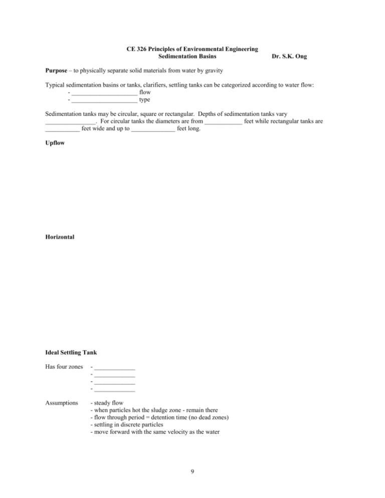
CE 326 Principles of Environmental Engineering Sedimentation Basins Dr. S.K. Ong Purpose – to physically separate solid materials from water by gravity Typical sedimentation basins or tanks, clarifiers, settling tanks can be categorized according to water flow: - _____________________ flow - _____________________ type Sedimentation tanks may be circular, square or rectangular. Depths of sedimentation tanks vary ________________. For circular tanks the diameters are from ____________ feet while rectangular tanks are ___________ feet wide and up to ______________ feet long. Upflow Horizontal Ideal Settling Tank Has four zones - _____________ - _____________ - _____________ - _____________ Assumptions - steady flow - when particles hot the sludge zone - remain there - flow through period = detention time (no dead zones) - settling in discrete particles - move forward with the same velocity as the water 9 To simply analysis, settling may be classified as: __________ Settling free settling, settling of particles as separate units and there is no apparent interaction between particles. Examples: presedimentation and settling of sand __________ Settling The particles flocculate during settling and increase in size and settle at a faster velocity. Examples: settling of coagulated waters, primary settling of municipal wastewater. __________ Settling zone settling or hindered settling. Settling of an intermediate concentration of particles where particles are so close together that interparticle forces hinder the settling of neighboring particles. Particles settle at a constant velocity. Therefore there will be a distinct solid-liquid interface between the settling particle mass and the clarified liquid. Examples: settling in the intermediate depths of water treatment clarifiers and wastewater treatment plant secondary clarifiers. ___________ Settling compression settling. Settling occur by compression of the compacting mass and interparticle liquid is squeezed out. Settling of particles of high concentrations. Examples: compression settling in lower depths of thickening clarifier for activated sludge plants Estimation of settling velocity of a particle (Type 1 settling only) A particle settling in water is subjected to the following forces: FG = gravitational force FB = Buoyancy force FD = Drag force When upward and downward forces are equal, particle will settle at a constant velocity called terminal velocity. Equating forces: _______________________________ FG = _________________ FB = _______________ s = density of particle (kg/m3) g = gravitational acceleration (m/s2) VP = volume of particle (m3) = density of fluid/water (kg/m3) CD = Drag coefficient AP = cross sectional area of particle (m2) Vs = terminal velocity (m/s) s g Vp - g Vp = CD Ap (Vs2/2) Assume the particle is spherical with a diameter d: VP = (/6) d3 AP = (/4) d2 9 FD = ___________________ d3 VP 2 6 d AP d 2 3 4 Then CD is dependent on the flow regime and is given by: Laminar flow Re < 0.5 CD = 24/Re Transition flow 0.5 < Re < 10,000 CD = 24/Re + 3/Re½ + 0.34 Turbulent flow Re > 10,000 CD = 0.4 Re = Reynolds number = d Vs/ where = kinetic viscosity (m2/s) = shape factor, to describe the nonspherical shape of the particle For particles falling under laminar conditions, CD = 24/Re = 24 / ( d Vs/) = 24 / d Vs Therefore Stoke’s Equation where = dynamic viscosity (Pa s-1) Typical Upflow Clarifier: Vs - rate at which the particle is settling Vo – flow of water upwards If Vs > Vo – ______________________ If Vs < Vo – ______________________ If Vs = Vo – _____________________ Because of flow of water is not uniform and there is a distribution of different particles and densities, , Vo is taken as < 80% of Vs in most settling tanks. Note that Vs is usually not known. 9 Vo (the average flow rate of the water) is given by: flow rate /surface area of the clarifier = ______________ m3/d/m2 = m/d (velocity unit) where As is the surface area of the clarifier Vo is termed as surface loading area (amount of flow per unit area) or overflow rate Note that the overflow rate for a horizontal clarifier is computed using the above equation. Design parameters - Summary - overflow rate or surface loading rate or clarification rate (m3/s/m2) - weir overflow rate (m3/d/m) Others - particle settling velocity Vs (m/s) - detention rate (hr) Notes the overflow rate is the average fluid velocity at about the mid section of the sedimentation tank. At the collection weir at the edge of the clarifier, the fluid velocity may be higher, resulting in a carry over of the particles. Therefore sufficient length must be provided to ensure that water will not rush over the weir. This lead to the second design parameter, weir overflow rate given by: = flow rate/length of weir = _______________ there is a distribution of particle sizes therefore will have a range or distribution of V s. Sedimentation tanks are usually not designed based on the settling velocities of the particle. Detention Time - approximately 2 - 8 hours (4 - 6 hours common)- some lime softening system has a retention time of 2 hours. Application Alum Iron Salts Lime Overflow Rate (gal/d/ft2) Weir Overflow Rate (gal/day/ft) 9 Sand Filters Purpose - used primarily to remove suspended particulate materials from water, example, silt and clay, microorganisms, colloidal and precipitated humic substances, alum or iron, calcium carbonate and magnesium hydroxide from lime softening, iron and manganese precipitates. Types of filters _________________ - solids are removed within the granular materials, example rapid granular-bed filters _________________ - solids are removed on the entering face of the granular material or filtering material, example, slow sand filters, membrane filters Design Parameters for rapid granular-bed filters 1. Loading rate or filtration rate, filtration velocity, V a = ______________ Where Q As = flow rate (m3/d) = surface area of filter (m2) Rapid Sand Filter Loading rates Conventional pretreatment using alum and iron salts/sand medium High rate with dual or triple media (anthracite coal layer) ______ gpm/ft2 (_________ m/h) _______gpm/ft2 (_________ m/h) 2. Practical maximum area of an individual gravity bed filter ____________ m2. 3. Minimum number of individual filter beds - two. When one is backwashing or under maintenance - the other bed must be capable of meeting water demands. 4. Total depth of and size of media Single media Dual media 5. graded sand Anthracite and sand 0.5 to 0.75 m Sand = 0.3 m, anthracite = 0.45 m Headloss calculations through the sand filter (equation , page 426) where hL = head loss through the filter, m Va = filtration rate m/s D = depth of filter sand, m fi = mass fraction of sand particles of diameter, d i di = diameter of sand grains of fraction i, m e = porosity = shape factor CD = drag coefficient CD f fi f f C D 1 C D 2 C D 3 .......... .. di d1 d2 d3 Initial head loss through media < 0.6 m Terminal head loss through media between 1.8 to 2.4 m 9 Note that the sand used usually has a range of sizes. To compute the head loss the sieve analysis (size distribution) is needed. If the sieve analysis is provided by the supplier use the sieve analysis (size distribution) by the supplier. However, some suppliers provide: Effective size, P10 – 10th percentile – size of sieve opening where 10% of the total mass would go through Uniformity Coefficient , U = P60/P10 The size distribution curve of the sand can be described by the following equation: Px = Xg (Sg)z where z = normal variate of the log normal curve (see Table below) x = percent of the fraction passing through the sieve Xg = geometric mean Sg = geometric standard deviation Fraction 0.1 0.2 0.3 0.4 0.5 0.6 0.7 0.8 0.9 Percent 10 20 30 40 50 60 70 80 90 Z -1.282 -0.842 -0.524 -0.253 0.000 0.253 0.524 0.842 1.282 Using P10 and U, Xg and Sg can be estimated using the following equations. With Xg and Sg the geometric distribution of the sand can be estimated. P10 = Xg (Sg)-1.282 U = P60/P10 = (Sg)1.535 Example: a sand has the following specifications, P10 = 0.40 mm, U = 1.40 Sg = (1.4)1/1.535 = 1.245 Xg = 0.40/(1.245)-1.282 = 0.530 mm For typical filter head loss calculations, the sand is divided into five different fractions (20% each). Therefore P30 = (0.530)(1.245)-0.524 = 0.472 mm 9 Problem 3 - 81 - Find head loss, given Depth D = 0.75 m, Ss = 2.80, = 0.91, e = 0.50, T = 5o C, Vs = 230 m3/d.m2 Step 1. Compute the filtration rate, in this problem it is given as Vs = 230 m3/d.m2 = _________________ m/s Step 2. Determine the geometric mean of sand particle for various fractions, for example, fraction retained by US sieve 8 - 12, d = (2.38)(1.68) = ___ mm Step 3. Determine Reynolds number Re Step 4. Compute CD, transition range use C D Step 5. Compute (CDfi/di) and sum all values Step. 6. Compute head loss using hL US Standard Sieve No 8 – 12 12 – 16 16 – 20 20 – 30 30 – 40 40 – 50 50 – 70 % retained 0 0.40 13.10 54.40 30.20 1.785 0.015 dvs (0.91)( 0.002 )( 2.66 x10 3 ) 3.70 1.307 x10 6 24 3 24 3 0.34 0.34 8.38 Re 3.70 Re 3.70 1.067 s2 D g 4 Sieve opening (upper) mm 2.38 1.68 1.19 0.84 0.59 0.42 0.297 C D f 1.067 (2.66 x10 3 ) 2 (0.75) 38628 .37 0.39 m d (0.91)(9.8)( 0.50 ) 4 Sieve opening (lower) mm 1.68 1.19 0.84 0.59 0.42 0.297 0.210 Geometric mean (mm) 2.00 1.41 1.00 0.70 0.50 0.353 0.250 9 R CD 3.704 2.611 1.852 1.296 0.926 0.654 0.463 8.378 11.39 15.5 21.49 29.37 40.75 56.6 CDf d 0 32.31 2030.5 16731.5 17739.5 2060.6 33.96 38628.37 6. Backwash Rate - backwash water needed to clean the filters, water may be provided from the clear well or from a separate backwash water tank - different approaches in estimating the backwash rate - typically _____________________________ m/d (___________________ gpm/ft2) - about 5 times more than the filter loading rates - expand bed by _______________________% - wash time is about ___________________ minutes, total time backwash filter (including preparation, draining, etc.) may take about _______________ minutes - for typical systems, amount of backwash water used should be between _____________% of filtered water produced - surface wash system – to ensure thorough cleaning and to prevent the formation of mud balls – provided for by directing jets of water downward on the surface of the filter media or by using rotating arms that sweep the surface of the filter. - air wash system – air introduced into the underdrain at a rate of ________________ m/min based on filter area. The rolling action of the air scours the deposits on the sand – releasing them. Backwash Rate Book’s approach - a back wash rate is selected which is equal to the settling velocity of the smallest particle that must be retained: where De = depth of the expanded bed, m e = porosity of the bed ee = porosity of expanded bed f i= mass fraction of sand with expanded porosity vb = backwash water velocity vs = settling velocity For a typical media of different sizes, divide the media into five different sizes and compute D ei for each size and sum up the bed expansion. 7. Placement of Backwash Trough - bottom of backwash trough should locate about _____________ m above the expanded bed, spacing of troughs approximately _____________ m. Rule of thumb - allow approximately _______________ m above the top of the sand for washwater troughs 8. Underdrain System (see Figure 3-40): Manifold and lateral underdrain system - first and oldest, not common now - high head loss - graded gravel needed Self supporting underdrain system - grouted to the filter floor - vitrified clay block False floor underdrain system - concrete floor or steel plate (usually in small filters or pressure filters) - located 1 to 2 feet above the bottom of the filter - nozzles are used to collect the water and the fine openings retain filter medium - no need for grout 9 Problem 3-82 - Find backwash rate and height of Backwash trough needed. Step 1. Determine the maximum backwash rate needed - must retain the finest sand of diameter 0.210 mm (0.025 cm or 0.00025 m) and density Ss = 2.80, from Figure 3 - 35, minimum settling velocity vs= 1.25 cm/sec (0.0125 m/s) or 1080 m/d Fraction size (m) Estimated Vs (cm/s) (Step 2) R (Step 3) CD (Step 4) vs (Step 5) ee (Step 6) f/(1-e) 0 0.004 0.1315 0.545 0.302 0.0178 0.00015 0.002 0.0014 0.001 0.0007 0.0005 0.00035 0.00025 20 18 15 10 7 5 3 278.5 175.4 104.4 49.7 24.4 12.2 5.22 0.61 0.72 0.86 1.26 1.93 3.17 6.25 0.185 0.14 0.11 0.076 0.052 0.0344 0.020 0.55 0.588 0.620 0.672 0.73 0.80 0.90 (step 7) 0 0.0089 0.246 1.66 1.118 0.089 1.5 x 10⁻⁵ 3.22 Step 2. Step 3 Step 4 Estimate settling velocities of each fraction of sand using Figure 3 - 35 dvs (0.91)(0.002 )(0.20) Estimated Reynolds number using Re 278 .5 1.307 x10 6 24 3 24 3 0.34 0.34 0.61 Compute CD , transition range use C D Re 278 .5 Re 278 .5 if in laminar or turbulence range use different equations 1/ 2 Step 5 Compute new vs using 4g(s )d 3C D 0.22 Step 6 Step 7 Step 8 Step 9 v 0.0125 Compute ee b v 0.185 s f Compute , sum up values 1 ee 1/ 2 4(9.8)( 2,800 1,000 )0.002 3(0.61)1,000 = 0.185 m/s 0.22 0.55 f (1 0.5)( 0.75 )(3.22 ) 1.21m 1 e Use a safety margin of 0.15 m, therefore the total height from the bottom of the trough to the bottom of the sand = 1.21 + 0.15 m = 1.36 m. Compute De from (1 e) D 9 Disinfectants Chlorine CE 326 Principles of Environmental Engineering Disinfectants Reactions CT values Reacts with water to form hypochlorous acid Cl2 + H2O <==> HOCl + H+ + ClHOCl <==> OCl- + H+ (HOCl - 100 times more effective than OCl-) In the presence of ammonia, forms chloramines NH3 + HOCl => NH2Cl + H2O monochloramine NH2Cl + HOCl =>NHCl2 + H2O dichloramine NHCl2 + HOCl => NCl3 + H2O trichloramine 2NH3 + 3HOCl =>N2(g) + 3HCl + 3H2O Advantages/Disadvantages free available chlorine between 70 - 200 for 99.9 % inactivation of Giardia depending on pH, temp., concentration - very strong oxidant - fairly inexpensive, easy to store and transport - chlorine concentration can be determined easily - persists in water - easy to store CT value for chlor-amines is approx. 1,850 - forms trihalomethanes (THMs) - poisonous gas - must be handled carefully - imparts odor to water at high concentrations 2.5 for 99.9 % inactivat-ion of Giardia at 10˚ C - very strong oxidant - leaves no residual, forms O2 - does not form THMs Free available residual chlorine combined available residual chlorine Ozone (O3) Ozone reacts with water to form OH• hydroxyl radicals, very strong oxidizing agent There are many reactions one of them is as follows: - expensive, generated on site by passing air or O2 through a corona discharge generated at high voltage - not persistent in water O3 + OH- => O3- + OH• 9 Chlorine dioxide (ClO2) - generated on site using chlorine and sodium chlorite Cl2 + 2NaClO2 => 2ClO2 + 2 NaCl 40 for 99.9 % inactivat-ion of Giardia at 10˚ C - does not form THMs - more effective than chlorine and over a broad pH range - provides a measurable residual - forms chlorite and chlorate in water, possible health risk - moderately expensive compared to chlorine - leaves tastes and odors Ultra Violet (UV) wavelength in the range of 0.2 to 0.39 µm, lamps protected by a quartz sleeve - no chemical addition - performs well for bacteria and viruses - penetrates only 50 to 80 mm, needs multiple tubes - expensive - no residual - water must be free from turbidity, lamps must be free from slimes and precipitation 9 CE 326 Water Treatment Plant Flow Diagram Raw Water Rapid Mix Important Design Criteria (i) ___________________ (ii) __________________ Slow Mix/ Flocculation Basin Sedimentation Tank/Clarifier Important Design Criteria (i) ___________________ (ii) __________________ Important Design Criteria (i) ___________________ (ii) __________________ Sand Filter Distribution Storage and disinfectant contact tank Important Design Criteria (i) ___________________ (ii) __________________ (iii)__________________ Important Design Criteria (i) ___________________ (ii) __________________ Supernatant back to rapid mix tank Sludge Settling Tank Sludge 9
