INR02-02
advertisement
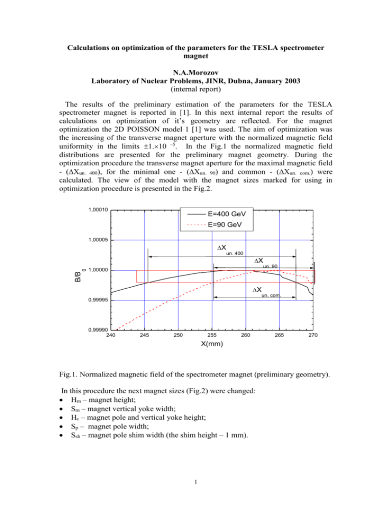
Calculations on optimization of the parameters for the TESLA spectrometer magnet N.A.Morozov Laboratory of Nuclear Problems, JINR, Dubna, January 2003 (internal report) The results of the preliminary estimation of the parameters for the TESLA spectrometer magnet is reported in [1]. In this next internal report the results of calculations on optimization of it’s geometry are reflected. For the magnet optimization the 2D POISSON model 1 [1] was used. The aim of optimization was the increasing of the transverse magnet aperture with the normalized magnetic field uniformity in the limits 1.10 –5. In the Fig.1 the normalized magnetic field distributions are presented for the preliminary magnet geometry. During the optimization procedure the transverse magnet aperture for the maximal magnetic field - (Xun. 400), for the minimal one - (Xun. 90) and common - (Xun. com.) were calculated. The view of the model with the magnet sizes marked for using in optimization procedure is presented in the Fig.2. 1,00010 E=400 GeV E=90 GeV 1,00005 X un. 400 0 B/B X un. 90 1,00000 X un. com. 0,99995 0,99990 240 245 250 255 260 265 270 X(mm) Fig.1. Normalized magnetic field of the spectrometer magnet (preliminary geometry). In this procedure the next magnet sizes (Fig.2) were changed: Hm – magnet height; Sm – magnet vertical yoke width; Hc – magnet pole and vertical yoke height; Sp – magnet pole width; Ssh – magnet pole shim width (the shim height – 1 mm). 1 40 Y(cm) 30 Hm 20 Sp 10 Sm Hc 0 0 10 20 Ssh 30 40 50 60 X(cm) Fig.2. The view of the model 1 (the sizes for optimization are marked). The results of calculations of the Hm, Sm, Hc and Sp influence on the magnetic field uniformity are presented accordingly in the Fig.3, 4, 5, 6. From those figures it is possible to notice the most powerful influence of the Hc parameter. In the Fig.7 the normalized magnetic field distributions are presented as optimized by means of Hc. Xun. 90 Xun. 400 Xun. com. 25 Xunif.(mm) 20 15 10 5 0 270 280 290 300 310 320 Hm(mm) Fig.3. The uniformity regions dependence from the magnet height. 2 330 un. 90 un. 400 un. com. 25 Xunif.(mm) 20 15 10 5 0 150 160 170 180 190 Sm(mm) Fig.4. The uniformity regions dependence from the magnet vertical yoke width. un. 90 un. 400 un. com. 35 30 Xunif.(mm) 25 20 15 10 5 0 110 120 130 140 150 160 170 Hc(mm) Fig.5. The uniformity regions dependence from the magnet pole and vertical yoke height. 3 un. 90 un. 400 un. com. 30 25 Xunif.(mm) 20 15 10 5 0 0 10 20 Sp(mm) Fig.6. The uniformity regions dependence from the magnet pole width. 1,00010 E=400 GeV E=90 GeV B/B0 1,00005 1,00000 Xun. com. 0,99995 0,99990 230 235 240 245 250 255 260 265 270 275 X(mm) Fig.7. Normalized magnetic field of the spectrometer magnet (optimized by means of Hc). It is well known from the dipole magnet technique that the using of the pole shims is rather effective in increasing the magnet aperture when the required magnetic field uniformity is in the range 1.10 –4 or more. The effect of such shims was studied for 4 the spectrometer magnet with the field uniformity 1.10 –5. In the model 1 such shims were inserted from one side of the magnet poles. Their height was 1 mm and the width Ssh was varying. The results of calculations of the Ssh influence on the magnetic field uniformity are presented in the Fig.8. The calculations show that for the field uniformity 1.10 –5 the pole shims are useless because of the magnet saturation effects. In the Fig.9 it is possible to see, that when the magnetic field uniformity for the maximal field level is optimal (Ssh =45 mm), for the minimal field the uniformity is far from optimal. 40 Xun. 90 Xun. 400 Xun. com 35 Xunif.(mm) 30 25 20 15 10 5 0 0 10 20 30 40 50 60 Ssh(mm) Fig.8. The uniformity regions dependence from the magnet pole shims width. The optimized geometry (cross section) of the TESLA spectrometer magnet is presented in the Fig.10. The 3D view of this magnet is presented in the Fig.11 (the coils front parts are removed).The normalized magnetic field for the final magnet geometry is presented in the Fig.12. The parameters of optimized spectrometer magnet are collected in the Tab.1. 5 1,00010 E=400 GeV E=90 GeV B/B0 1,00005 1,00000 0,99995 0,99990 230 235 240 245 250 255 260 265 270 275 280 X(mm) Fig.9. Normalized magnetic field of the spectrometer magnet (Ssh =45 mm). 40 Y(cm) 30 20 10 0 0 10 20 30 40 50 60 X(cm) Fig.10. The cross-sectional view of the optimized geometry of the TESLA spectrometer magnet. 6 Fig.11. The 3D view of the spectrometer magnet (the sizes are in mm). 1,00010 E=400 GeV E=90 GeV B/B0 1,00005 1,00000 Xun. com. 0,99995 0,99990 230 235 240 245 250 255 260 265 270 X(mm) Fig.12. Normalized magnetic field of the spectrometer magnet (optimized geometry). 7 Table 1. The main technical parameters of the TESLA spectrometer magnet (optimized geometry). Magnetic field (min/max) (Т) Pole gap (mm) Yoke type Yoke sizes (mm) Yoke weight (t) А*turns (1 coil) (max) Turns number (1 coil) Conductor type Coils current (max) (А) Current density (max) (A/mm 2) Coils voltage (max) (V) Coils power dissipation (max) (kW) Number of water cooling loops The length of one cooling loop (m) Water input pressure (Bar) Water input temperature (deg C) Temperature rise (deg C) 0.1/0.44 35 C 3955603000 4.51 6335 6*4=24 Сu, 12.512.5, 7.5 264 2.4 13.3 3.5 12 28 4 20 0.55 Conclusions With the purpose of increase of the horizontal aperture of the spectrometer magnet the calculations on optimization of its yoke shape were carried out. The modified geometry of the magnet was determined, allowed to increase the horizontal aperture in the working range of magnetic fields up to 19 mm (relative uniformity of the magnetic field - 1.10 –5). References [1] N.A.Morozov. The preliminary estimation of the parameters for the TESLA spectrometer magnet. LNP, JINR, Dubna, December 2002, (internal report). 8
