Radiative Transfer Equation
advertisement
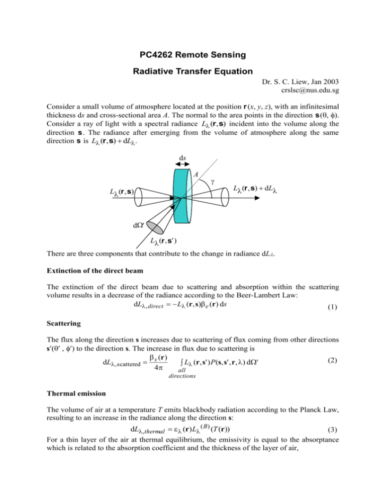
PC4262 Remote Sensing Radiative Transfer Equation Dr. S. C. Liew, Jan 2003 crslsc@nus.edu.sg Consider a small volume of atmosphere located at the position r (x, y, z), with an infinitesimal thickness ds and cross-sectional area A. The normal to the area points in the direction s (. Consider a ray of light with a spectral radiance L (r , s) incident into the volume along the direction s . The radiance after emerging from the volume of atmosphere along the same direction s is L (r , s) dL. ds A L (r , s) L (r , s) dL d' L (r , s' ) There are three components that contribute to the change in radiance dL Extinction of the direct beam The extinction of the direct beam due to scattering and absorption within the scattering volume results in a decrease of the radiance according to the Beer-Lambert Law: dL, direct L (r, s) e (r ) ds (1) Scattering The flux along the direction s increases due to scattering of flux coming from other directions sto the direction s. The increase in flux due to scattering is (r ) (2) dL, scattered s L (r, s' ) P(s, s' , r, ) d' 4 all directions Thermal emission The volume of air at a temperature T emits blackbody radiation according to the Planck Law, resulting to an increase in the radiance along the direction s: dL, thermal (r) L ( B) (T (r)) (3) For a thin layer of the air at thermal equilibrium, the emissivity is equal to the absorptance which is related to the absorption coefficient and the thickness of the layer of air, (r) (r) a (r, ) ds (4) Hence, the increase in radiance due to thermal emission is dL, thermal a (r, ) L ( B) (T (r)) ds (5) Radiative Transfer Equation (RTE) Putting the three components together, the change in radiance along the direction s is (r, ) dL e (r, ) L (r, s)ds s 4 B P(s, s' ; r, ) L (r, s' ) d' ds a (r, ) L (T (r )) ds (6) all direction Notes: 1. If the material within the scattering volume is homogeneous, then the scattering phase function is dependent only on the scattering angle , given by cos( ) s' s (7) 2. The absorption, scattering and extinction coefficients are related by e s a (8) Recall that the single scattering albedo is the ratio of the scattering to the extinction coefficients: (9) s e Hence, the scattering and absorption coefficients can be expressed in terms of the extinction coefficient and the single scattering albedo, s e ; a (1 )e (10) Dividing both sides of Eqn. (6) by e (r, ) ds and rearranging, we get the radiative transfer equation (RTE): dL (r, s) 1 L (r, s) J (r, s) e (r, ) ds (11) The RTE has a source function J (r, s) that is the sum of two terms: a scattering source function J S (r, s) and an emission source function J E (r, s) , J (r, s) J S (r, s) J E (r, s) (12) The scattering source function is J S (r, s) (r, ) 4 (13) P(s, s' ; r, ) L (r, s' )d' all direction The thermal emission source function is J E (r, s) 1 (r, )L B (T (r )) (14) Radiative Transfer Equation in Vector Notations The RTE can be written in a compact form as: 1 s L (r, s) L (r, s) J (r, s) e (r, ) (15) Radiative Transfer Equation in the Cartesian Coordinates System z s r x y In the Cartesian coordinate system, the RTE has the form: 1 cos x cos y cos z L ( x, y, z; s) e ( x, y , z , ) x y z L ( x, y, z; s) (16) J ( x, y , z ; s ) where x , y and z are the angles between the directional vector s and the x-, y- and z-axes respectively. RTE for a Plane-Parallel Atmosphere z A thin horizontal layer of atmosphere above the ground, Height z > 0, Optical Thickness 0 < < 0 s Ground Level, z = 0, = 0 y x In this approximation, the atmosphere is assumed to be homogeneous along the x and y directions (i.e. along the horizontal plane) and varies only along the z-direction (i.e. the upward vertical direction). The directional vector s is parameterized by the zenith angle and the azimuthal angle while the positional vector r is parameterized by only the z coordinate. The RTE is reduced to cos d L ( z; , ) L ( z; , ) J ( z; , ) e ( z ) dz (17) When viewed from the top of the atmosphere, it is more convenient to deal with the optical thickness, instead of the physical thickness of the atmosphere. The optical thickness at height z as seen from the top of atmosphere is defined as, ( z , ) e ( z ' , )dz ' (18) z When defined in this way, the optical thickness is a decreasing function of the height above the ground. At the top of the atmosphere (z = ), the optical thickness is zero. At the ground level (z = 0), the total optical thickness of the atmosphere is 0 () e ( z ' , )dz ' 0 (19) Top of the atmosphere, z = , = 0 ( z , ) e ( z ' , )dz ' z z Ground level, z = 0, = It is also more convenient to work with the cosine of the zenith angle, u cos() (20) Note that u is positive (0<u<1) for upward direction (0 < < /2) and negative (–1<u<0) for downward direction (/2 < < ). Upward Directions, 0 < < /2 0<u<1 Downward Directions, /2 < < -1 < u < 0 Using the new coordinates and u, the RTE for the plane parallel atmosphere can be expressed in the form d (21) u L (; u , ) L (; u , ) J (; u , ) d The source functions are: J S (, u, ) (, ) 2 1 P(u, , u ' , ' , , ) L (, u ' , ' ) du ' d' 4 0 -1 J E (, u, ) 1 (, )L B (T ()) (22) (23)
