Light Scattering
advertisement
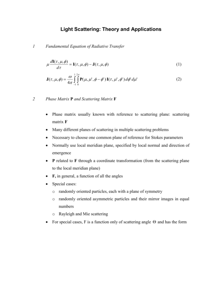
Light Scattering: Theory and Applications 1 Fundamental Equation of Radiative Transfer dI( , , ) I( , , ) J ( , , ) d J( , , ) 4 2 (1) 1 2 P( , ' , ' ) I( , ' , ' ) d ' d ' (2) 1 0 Phase Matrix P and Scattering Matrix F Phase matrix usually known with reference to scattering plane: scattering matrix F Many different planes of scattering in multiple scattering problems Necessary to choose one common plane of reference for Stokes parameters Normally use local meridian plane, specified by local normal and direction of emergence P related to F through a coordinate transformation (from the scattering plane to the local meridian plane) F, in general, a function of all the angles Special cases: o randomly oriented particles, each with a plane of symmetry o randomly oriented asymmetric particles and their mirror images in equal numbers o Rayleigh and Mie scattering For special cases, F is a function only of scattering angle and has the form F11 F 12 0 0 F12 0 F22 0 0 F33 0 F34 0 0 F34 F44 Isotropic Rayleigh scattering: F11 F22 3 (1 cos 2 ) 4 F33 F44 3 cos 2 3 F12 F21 sin 2 4 Mie scattering: F11 F22 , F33 F44 3 Scattering Behavior in Different Regimes [Fig. 5, Hansen and Travis] Rayleigh scattering o strong positive linear polarization ( F21 / F11 ), with a maximum at 90° scattering angle Geometric optics o small scattering angles: phase function large and linear polarization small because diffracted light is predominant o other than diffraction, most of the light scattered into forward hemisphere due to rays passing through particle with two refractions => negative linear polarization (Fresnel’s equations) o positive linear polarization at ~ 80-120° scattering angle: reflection from outside of particles o positive polarization maximum at ~ 150° scattering angle (primary rainbow): internal reflection – scattering angle has a maximum as a function of the incident angle on the particle; weaker feature at ~ 120° scattering angle (secondary rainbow): two internal reflections – scattering angle has a minimum as a function of the incident angle on the particle o maximum in backscattering direction (glory): incident edge rays Transition region in between o linear polarization complicated function of size parameter o as size parameter decreases, degree to which paths of separate light rays can be localized decreases o secondary rainbow, with a more detailed ray path, lost from polarization before primary rainbow o primary rainbow becomes blurred with decreasing size parameter 4 Effect of Nonsphericity [Figure 1, Mishchenko et al.] Define F11 ( spheroid ) / F11 ( sphere) . There are five distinct regions: Nearly direct forward scattering o ρ~1 o region least sensitive to particle sphericity because diffraction dominates and is determined by the average area of the particle geometrical cross section ~10 to 30° scattering angle o ρ>1 o ratio increases with increasing aspect ratio ε ~30 to 90° scattering angle o ρ<1 o region becomes narrower with increasing ε o ratio decreases with increasing ε ~90 to 150° scattering angle o ρ >> 1 o strongly enhanced side scattering as opposed to deep and wide side scattering minimum in spherical particles o region becomes wider with increasing ε ~150 to 180° scattering angle o ρ << 1 o strong rainbow and glory features suppressed by nonsphericity In general, the polarization generated by spheroids is more neutral than that for spheres and shows less variability with size parameter and scattering angle [Figure 10.6, Mishchenko et al.]. >~60° scattering angle o degree of linear polarization p is strongly ε-dependent o deviation from spherical behavior becomes more pronounced with increasing ε o Lorenz-Mie theory inappropriate for nonspherical particles in this region <~60° scattering angle o p weakly dependent on particle shape ~120° scattering angle o most prominent polarization feature for spheroids: bridge of positive polarization, which separates two regions of negative or neutral polarization at small and large scattering angles o bridge absent in spherical particles 5 Global Climatology of Aerosol Types [Figure 2] Seven basic aerosol types: sulfate(land/water), seasalt, carbonaceous, black carbon, mineral dust (accumulated/coarse) Each mixing group is a combination of 4 aerosol components Lognormal distribution 6 Phase Function for Kahn Mixing Group Types 7 Linear Polarization for Kahn Mixing Group Types 8 Radiative Effect I: Weighting Functions in 0.76 µm O2 A Band 8 Normalized Jacobian 6 4 2 0 -2 Type 1a 1b 1c 2a 2b 3a 3b 4a 4b 4c 5a 5b 5c -4 -6 -8 -10 0.758 0.760 0.762 0.764 0.766 0.768 0.770 0.772 Wavelength [m] 9 Radiative Effect II: Weighting Functions in 1.61 µm CO2 Band Normalized Jacobian 0.4 Type 1a 1b 1c 2a 2b 3a 3b 4a 4b 4c 5a 5b 5c 0.2 0.0 -0.2 -0.4 1.590 1.595 1.600 1.605 1.610 Wavelength [m] 1.615 1.620 10 Radiative Effect III: Weighting Functions in 2.06 µm CO2 Band Type Normalized Jacobian 0.10 0.05 0.00 1a 1b 1c 2a 2b 3a 3b 4a 4b 4c 5a 5b 5c -0.05 -0.10 2.08 2.07 2.06 2.05 2.04 Wavelength [m] Reducing Mixing Group Types Using SSA and Extinction Behavior Single Scattering Albedo 11 1.00 0.95 0.90 Type 1a 1b 1c 2a 4a 0.85 Group 1 0.80 Single Scattering Albedo 0.755 0.785 1.56 1.65 2.03 2.09 1.00 1.00 0.95 0.95 0.90 0.90 Type Type 2b 4b 4c 0.85 0.80 0.755 0.785 1.56 1.65 2.03 2.09 0.85 3a 5a 5c Group 2 0.755 Group 3 0.80 0.785 1.56 1.65 2.03 2.09 1.00 Single Scattering Albedo 1.00 Type Group 4 5b 0.95 Type Group 5 3b 0.95 0.90 0.90 0.85 0.85 0.80 0.80 0.755 0.785 1.56 1.65 2.03 2.09 0.755 Wavelength [m] 0.785 1.56 1.65 2.03 2.09 Normalized Extinction Coefficient 1.1 1.0 0.9 0.8 0.7 0.6 0.5 0.4 0.3 0.2 0.1 Group 1 Type 1a 1b 1c 2a 4a Normalized Extinction Coefficient 0.755 1.1 1.0 0.9 0.8 0.7 0.6 0.5 0.4 0.3 0.2 0.1 Normalized Extinction Coefficient 1.56 1.65 2.03 2.09 Group 3 Group 2 Type Type 2b 4b 4c 0.755 1.1 1.0 0.9 0.8 0.7 0.6 0.5 0.4 0.3 0.2 0.1 0.785 3a 5a 5c 0.785 1.56 1.65 2.03 2.09 0.755 0.785 1.56 1.65 2.03 1.1 1.0 0.9 0.8 0.7 0.6 0.5 0.4 0.3 0.2 0.1 2.09 1.1 Group 5 1.0 Group 4 0.9 0.8 0.7 0.6 0.5 0.4 0.3 0.2 0.1 Type Type 3b 5b 0.755 0.785 1.56 1.65 2.03 2.09 0.755 Wavelength [m] 0.785 1.56 1.65 2.03 2.09 Figure 2. Global Climatology of Aerosols (Kahn et al., 2001)
