Four Wire Measurement
APPENDIX A
WHY SO MANY TERMINALS?
(Understanding impedance measurement techniques)
by Henry P. Hall, Senior Staff Scientist, GenRad, Concord, MA
Automatic test systems that check components “in-circuit” have reawakened interest in multi-terminal
techniques for measuring impedance, initially developed for laboratory applications. State-of-the-art impedance
measurement methods, incorporated in complex bridge configurations, use as many as “four-pair” (or eightterminals) for determining a single component value.
Starting with “two-terminal: an working up to “eight-terminal” techniques, this article explores multiterminal methods for measuring impedance, indicating types of errors and typical applications for each method. To
illustrate these methods, the following discussion uses ideal voltmeters and ammeters (i.e.—the voltmeter does not
draw current and the ammeter does not develop voltage). Commercial instruments using either bridge or meter
techniques are not ideal and will contribute additional errors. Negligible in most applications, inaccuracies
introduced by these meters can often be measured and corrected for in the equations.
Two terminal measurements
The two-terminal technique (the
simplest method) can make very accurate
measurements on medium value impedances.
This technique applies a current and measures a
voltage and since only two terminals are
available the current source and voltmeter
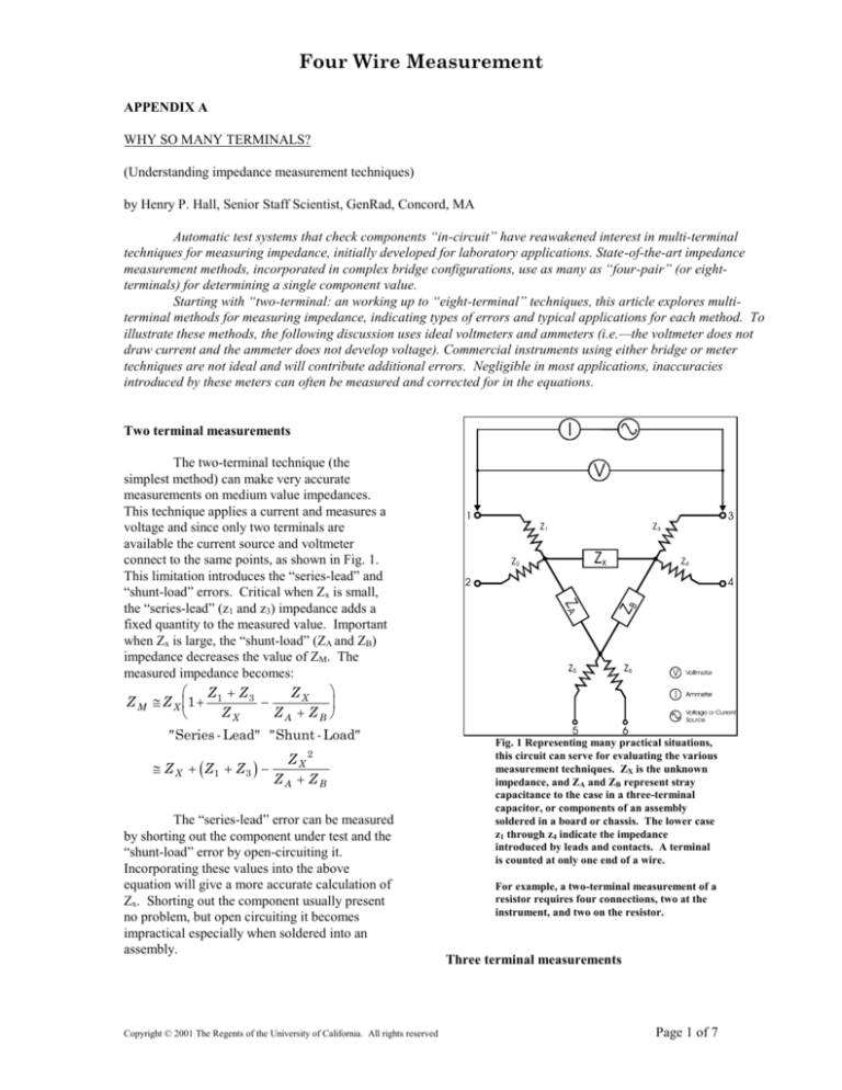
connect to the same points, as shown in Fig. 1.
This limitation introduces the “series-lead” and
“shunt-load” errors. Critical when Zx is small,
the “series-lead” (z1 and z3) impedance adds a
fixed quantity to the measured value. Important
when Zx is large, the “shunt-load” (ZA and ZB)
impedance decreases the value of ZM. The
measured impedance becomes:
Z Z3
ZX
Z M Z X 1 1
ZX
ZA ZB
"Series - Lead" "Shunt - Load"
ZX
ZX2
Z1 Z 3
ZA ZB
The “series-lead” error can be measured
by shorting out the component under test and the
“shunt-load” error by open-circuiting it.
Incorporating these values into the above
equation will give a more accurate calculation of
Zx. Shorting out the component usually present
no problem, but open circuiting it becomes
impractical especially when soldered into an
assembly.
Copyright © 2001 The Regents of the University of California. All rights reserved
Fig. 1 Representing many practical situations,
this circuit can serve for evaluating the various
measurement techniques. ZX is the unknown
impedance, and ZA and ZB represent stray
capacitance to the case in a three-terminal
capacitor, or components of an assembly
soldered in a board or chassis. The lower case
z1 through z4 indicate the impedance
introduced by leads and contacts. A terminal
is counted at only one end of a wire.
For example, a two-terminal measurement of a
resistor requires four connections, two at the
instrument, and two on the resistor.
Three terminal measurements
Page 1 of 7
Four Wire Measurement
Typically termed “guarded” or “direct”,
and excellent for evaluation high impedance, the
three-terminal technique differs from the twoterminal method because it applies a voltage and
measures a current, with each device connected
to different points (the voltage source to pont1
and the ammeter to point 3) as shown in Fig. 2.
The third terminal (“guard”) serves as a common
connection for input voltage and output current.
Impedance from point A or B to the “guard”
(point C) has no effect on the measurement, but
the “series-lead” impedances (z1, z3 and z5)
contribute errors as shown in the following
equation:
Z Z3
Z
Z
Z Z
Z M Z X 1 1
1 3 5 N
ZX
ZA ZB ZA ZB
"series lead"
"series /
shung"
"guard lead"
If z1, z3 and z5 were zero, then ZM=ZX,
eliminating any effect from ZA or ZB. The
impedance from point 1 to 5 will load the input
voltage, however the readings are still valid,
since this loading does not affect the measured
value, but only decreases the sensitivity of the
measurement.
Adding the “guard” introduces the
“series/shunt” and “guard-lead” errors. Caused
by a dividing effect from z1/ZA and z3/ZB,
“series/shunt” (a constant percent error) is
independent of Zx and very small at low
frequencies, if ZA and ZB just represent stray
capacitance.
Generally much smaller than the “shuntload” error in two-terminal measurements, the
“guard-lead” error becomes critical when Zx is
large. For example, in precision measurements
of low-loss three-terminal capacitors using long
shielded leads, capacitances ZA and ZB can be
quite large, and any resistance in the guard
connection causes a negative resistance across
Zx. The resultant negative conductance reading
on a bridge could confuse the engineer making
the measurement.
Many traditional four-arm bridges make
fair three-terminal measurements, since they will
tolerate some loading across a bridge arm.
Using a “Wagner guard” in the
wheatstone bridge (Fig. 3) removes the shunt
loading effects due to RA and RB with the
auxiliary balance RP.
Copyright © 2001 The Regents of the University of California. All rights reserved
Some a.c. bridges have used similar
guard circuits, however, most bridges now use
precision transformers (Fig.4) for accurate ratios
and immunity from shunt loading. Using a dual
output winding, id-loading effects reduce one
output voltage, the other is reduced because of
the coupling between the windings, making the
effective source impedance only the winding
resistance and leakage inductance, both typically
very small.
Another technique for reducing shunt
effects uses an inverting amplifier and feedback
resistor, (Fig. 5) with the input to the amplifier at
a “virtual-ground”. The effective impedance to
ground becomes the feedback resistance divided
by the open-loop gain, resulting in very small
errors.
A “double-guard” technique (Fig. 6)
eliminates the “guard-lead” error by putting these
impedances in series with the other lead
impedances, and results in no “shunt” error, with
the “guard-lead” error generally very small.
What is Impedance?
Similar to friction causing a moving
object to slow down a current flowing between
two pints of an electronic circuit will develop a
voltage, if it encounters anything that tends to
impede its free flow, such as Resistors, Capacitor
and Inductors. This effect is measured in ohms
in accordance with Ohm’s law:
Z
V
where V = voltage, I = current, Z=impedance
I
The impedance resulting from resistors
is called “resistance” (R), that from capacitors
“capacitive reactance” (XC) and that from
inductors “inductive reactance” (XL). These
components of impedance are defined by the
following equations
Fig. 2 Typically termed “guarded” or “direct”, and
excellent for evaluating high impedance, this three-
Page 2 of 7
Four Wire Measurement
terminal measuring technique eliminates the “shuntlead” error encountered in ‘two-terminal”
measurements.
The “double-guard” is rarely required, except in
in-circuit testing when ZA and ZB are low values.
Measured impedance with this “double-guard”
becomes:
Z Z 3 Z 5 Z 6 Z1 Z 5 Z 3 Z 6
Z M Z X 1 1
ZX
ZA
ZB
Four terminal measurements
Fig. 3 Using a “Wagner guard”, this three-terminal
Wheatstone bridge circuit makes precise measurements
by removing shunt loading effects from RA and RB.
Ideal for measuring low impedance, the
four-terminal measurement technique (Fig. 7)
applies current through one pair of leads and
measures voltage on the other pair, removing the
“series-lead” impedance error completely. The
measured impedance, ZM, shown in the following
equation, only includes the “shunt-load” error.
ZX
Z M Z X 1
ZA ZB
"shunt - load"
Fig. 4 Using a precision transformer, this three-terminal
a.c. bridge circuit maintains an accurate voltage ratio in
spite of shunt loading.
Fig. 5 With an inverting amplifier and feed-back resistor
(Rs) this three-terminal impedance measurement
technique places the input voltage to the amplifier (e a) at
a “virtual-ground”, resulting in very small errors due to
CB.
R
V
where:
I
For simplicity, Fig. 7 does not display
the effects of mutual inductance between leads,
critical in a.c. measurements. Using coaxial
cable or twisted pair leads will reduce these
effects.
Used for precision dc resistance
measurements, the Kelvin bridge configuration
(Fig. 8) is the best known four-terminal
technique. The Kelvin bridge has a main adjust
(RA) with auxiliary adjustments for “Yoke”, Ra
(corrects for r3 and r4) and “lead-adjust” Rb
(corrects for r2). The term “Kelvin-connection”
is often used interchangeably with “fourterminal”.
f = frequency
j = ac phase component.
XC
C = capacitance (Farads)
L = inductance (Henry’s)
R = resistance (Ohms)
V
1
j
I
j 2 f C 2 f C
XL
V
j 2 f L
I
Copyright © 2001 The Regents of the University of California. All rights reserved
Fig. 6 Adding a “double-guard” to the three-terminal
technique, this circuit eliminates the “guard-lead” error.
Page 3 of 7
Four Wire Measurement
High input-impedance differential
amplifiers, which reduce “series-lead”
errors.
Five terminal measurements
Capable of making precise
measurements over a wide rage of impedance,
the five-terminal method (Fig. 9) integrates threeterminal techniques for high impedance and fourterminal techniques for low impedance. Used
primarily for remote and in-circuit evaluations
this method eliminates both the “series-lead” and
“shunt-load” errors found in two-terminal
measurements, leaving much smaller errors
caused by the interaction of series and shunt
impedance. The measured impedance becomes:
Fig. 7 For measuring low impedance, this four-terminal
technique removes the “series-lead” impedance error.
Z3
Z M Z X 1
ZB
"series /
shunt"
Z5 Z X
ZA ZB
"guard lead"
Measured Impedance
If a network contains a component with
an impedance ZX, any impedance measurement
on that network will give a result ZM in the form,
ZM
Fig. 8 Making precision four-terminal resistance
measurements this “Kelvin bridge” uses three
adjustments for nulling out effects from leads and
contacts.
Z X 1 A B
1 C ZX
where A, B, and C depend on other impedances
of the network. If you make a reasonably good
measurement of ZX, then A, B and C will be
small compared to unity and you can
approximate the measured value as:
Some other four-terminal techniques include:
The “potentiometer” method which uses
voltage ratio measurements, calculating the
result using the measured ratios.
Transformers for ac measurements supply
compensating voltages which reduce errors
analogous to the three-terminal technique as
shown in Fig. 4.
Copyright © 2001 The Regents of the University of California. All rights reserved
Page 4 of 7
Four Wire Measurement
B
Z M Z X 1 A
C ZX
ZX
Examples in this article use this approximation
for ZM with the values for A, B and C dependent
on z1 through z6, ZA and ZB.
Six terminal measurements
Fig. 9 Capable of making precise measurements over a
wide range of impedances, this five-terminal technique
integrates three and four-terminal methods, eliminating
both the “series-lead” and “shunt-lead” errors.
Eliminating the “guard-lead” errors, the
six-terminal technique (Fig. 10) is an extension
of the five-terminal, adding a second guard, as
previously described for three-terminal
measurements. ZM for this configuration is:
Z Z6
Z M Z X 1 3
ZB
"series / shunt"
Fig. 10 With “guard” points, this six terminal method
removes the “guard-lead” error encountered in fiveterminal measurements.
A typical configuration for a sixterminal measurement uses an operational
amplifier and two differential amplifiers (Fig.11).
The addition of these active components helps
reduce the effects of leads, contacts, mutual
inductance and stray capacitance.
What about eight terminals?
Fig. 11 Incorporating an operational amplifier and two
differential amplifiers, this six-terminal circuit makes
very accurate impedance measurements.
Used by the National Bureau of
Standards (NBS), the eight terminal method
involves four-pairs configured to attain better
than on e part in 108. (see Fig. 12) Shielded
coaxial connections reduce mutual inductance
between leads and prevent electrostatic/
electromagnetic pickup. The test network has no
errors but shielded cables add capacitance across
the meter terminals, making the measured
impedance:
Z Z7 Z3 Z 6
Z M Z X 1 2
Z 27
Z 36
Fig. 12 Used by the National Bureau of Standards, this
eight-terminal measures ZX in the network without
errors.
Copyright © 2001 The Regents of the University of California. All rights reserved
The errors due z2, z3 z6 and z7 are
extremely small. For example, 50 cable
(RG58/U) has about 30 pF and 11m per foot,
with the resulting errors being a few parts in 109
for one foot leads at 1KHz. Easily measured, this
error can be corrected for, if necessary.
Page 5 of 7
Four Wire Measurement
Impedance Measurements with
Automatic Test Systems
Functional testing of loaded boards with
automatic systems does not necessarily involve
impedance measurement. But these automatic
systems do often incorporate digital multimeters
that can measure resistance and, to meet custom
requirements may include impedance bridges.
On the other hand, automatic in-circuit
test systems that evaluate components on loaded
boards, must have multi-terminal impedance
measurement capability to isolate the component
under test from the effects of adjacent circuitry.
Most of these systems include the three-terminal
technique, using the third terminal as a “guard”
point to place selected nodes at an equipotential,
thereby removing the effects of components
connected between these nodes. This method is
adequate for detecting manufacturing faults and
wrong components. Some firms now use four,
five and even six-terminal techniques for
increased accuracy. Future equipment designs
could conceivably involve widespread use of sixterminal techniques, but the added wiring and
switching would substantially increase equipment
costs.
A thorough description of these incircuits testers will be presented as part of a
feature article on automatic test systems in the
March 1979 issue of Electronics Test.
This causes a 10% error in the measured
value Zx. Increasing demand for more accurate
in-circuit tests could result in wide spread use
and better implementation of six-terminal
impedance measurement techniques in automatic
systems.
Now a senior staff scientist, Henry Hall has
designed several of Gen Rad’s impedance
measuring instruments and standards. In his 30
years at Gen Rad, he has served as an Engineer,
a leader of the Low Frequency Impedance
Measurements group, Engineering Staff
consultant and Senior Principle Engineer. A
member of Phi Beta Kappa, Tau Beta Pi, Eta
Kappa Nu, Sigma Xi and a Fellow of the IEEE,
he received a B.A degree from Williams College,
and a B.S. and M.S. degrees in electrical
engineering form the Massachusetts Institute of
Technology.
References
1.
2.
Conclusions
3.
The most difficult impedance
measurements are those on components “in-situ”,
that is, soldered in a network with other
components. It’s easy to imagine values or
combinations of components in the circuit of
Fig. 1, which would make it impossible to
measure ZX accurately with available
instrumentation. However, today’s techniques
and instruments can measure a good percentage
of the components on a typical assembly.
For instance if ZX = 10K and
z5 = 1m in the circuit of Fig. 2 the “guard-lead”
error becomes:
Z 5 Z X 0.00110.000
01
.
ZA ZB
1010
Copyright © 2001 The Regents of the University of California. All rights reserved
4.
5.
6.
7.
H. W. Bode, Network Analysis and
Feedback Amplifier Design, Van Nostrand,
New York 1945, p. 233.
G. F. C. Searle “On Resistances with Current
and potential Terminals,” The Electrician
No 1715, March 31, 1911, or see H.P. Hall
“A Technique for Avoiding Connection
Errors in Computerized Impedance
Measuring Systems,” IEEE Transactions on
Instrumentation and Measurement Vol 1M20 No. 4, November 1971, p.249
H. P. Hall “ The Measurement of
Electrolytic Capacitors”, GR Experimenter,
Vol. 40, No. 6, June 1966
T. R. Foord, R. C. Lanlands and A. J.
Binnie, “Transformer-Ration Bridge
Network with Precise Lead Compensation”,
Proc. Of the IEE (England), Vol. 110, No.
9, p. 86, September 1963.
MIT Staff, Electric Circuits, John Wiley and
Sons, New York, 7th Edition 1943, p. 146 or
see most any electrical engineering reference
handbook.
N. M. Tallan, H. C. Graham and R.V. West,
“Origin of Apparent Negative Impedance in
Three-Terminal Measurements.” Review of
Sci. Inst. Vol.33, No. 10, October 1962.
M. C. MacGregor, J. F. Hersh, R. D.
Cutkosky, F. K. Harris and F. R. Kotter,
“New Apparatus at the National Bureau of
Standards for Absolute Capacitance
Page 6 of 7
Four Wire Measurement
Measurements, IRE (IEEE) Transactions on
Instrumentation & Measurement, Vol. 1-7,
p.253, December 1958.
8. J. J. Hill and A. P. Miller, “An AC Double
Bridge with Inductively Coupled Ratio Arms
for Precision Platinum Resistance
Thermometry”, Proc. IEE (Eng.) Vol. 110,
No. 2, p. 453, 1963.
9. J. F. Hersh, “Connection Errors in
Inductance Measurements,” GR
Experimenter, Vol. 34, No. 10, October
1960.
10. R. D. Cutkosky, “Four-Terminal-Pair
Networks as Precision Admittance and
Impedance Standards” Communications and
Electronics, Vol. 70, p.19, January 1964.
11. R. D. Cutkosky, “Techniques for Comparing
Four-Terminal-Pair Admittance Standards”
NBC Journal of Research, C (Eng. &
Instrumentation), Vol. 74C, Nos. 3 and 4,
July-December 1970
Copyright © 2001 The Regents of the University of California. All rights reserved
Page 7 of 7


