LAB 2: Projectiles - University of San Diego Home Pages
advertisement
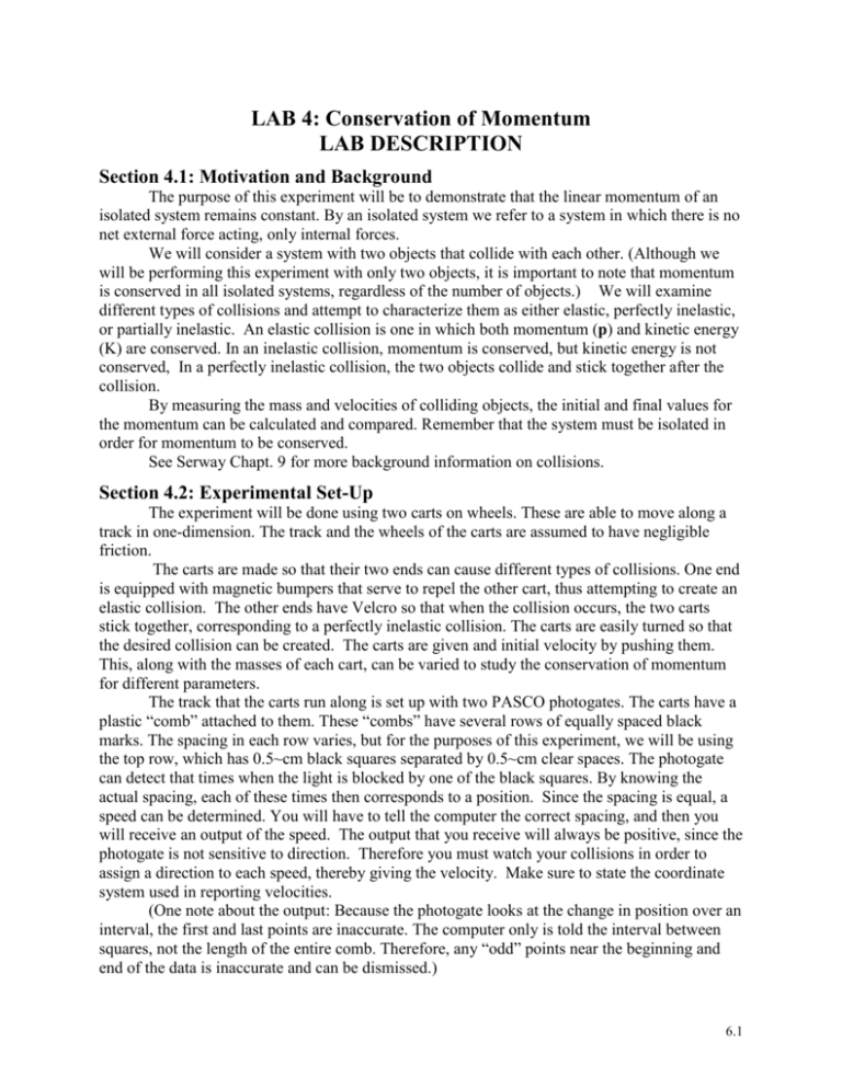
LAB 4: Conservation of Momentum LAB DESCRIPTION Section 4.1: Motivation and Background The purpose of this experiment will be to demonstrate that the linear momentum of an isolated system remains constant. By an isolated system we refer to a system in which there is no net external force acting, only internal forces. We will consider a system with two objects that collide with each other. (Although we will be performing this experiment with only two objects, it is important to note that momentum is conserved in all isolated systems, regardless of the number of objects.) We will examine different types of collisions and attempt to characterize them as either elastic, perfectly inelastic, or partially inelastic. An elastic collision is one in which both momentum (p) and kinetic energy (K) are conserved. In an inelastic collision, momentum is conserved, but kinetic energy is not conserved, In a perfectly inelastic collision, the two objects collide and stick together after the collision. By measuring the mass and velocities of colliding objects, the initial and final values for the momentum can be calculated and compared. Remember that the system must be isolated in order for momentum to be conserved. See Serway Chapt. 9 for more background information on collisions. Section 4.2: Experimental Set-Up The experiment will be done using two carts on wheels. These are able to move along a track in one-dimension. The track and the wheels of the carts are assumed to have negligible friction. The carts are made so that their two ends can cause different types of collisions. One end is equipped with magnetic bumpers that serve to repel the other cart, thus attempting to create an elastic collision. The other ends have Velcro so that when the collision occurs, the two carts stick together, corresponding to a perfectly inelastic collision. The carts are easily turned so that the desired collision can be created. The carts are given and initial velocity by pushing them. This, along with the masses of each cart, can be varied to study the conservation of momentum for different parameters. The track that the carts run along is set up with two PASCO photogates. The carts have a plastic “comb” attached to them. These “combs” have several rows of equally spaced black marks. The spacing in each row varies, but for the purposes of this experiment, we will be using the top row, which has 0.5~cm black squares separated by 0.5~cm clear spaces. The photogate can detect that times when the light is blocked by one of the black squares. By knowing the actual spacing, each of these times then corresponds to a position. Since the spacing is equal, a speed can be determined. You will have to tell the computer the correct spacing, and then you will receive an output of the speed. The output that you receive will always be positive, since the photogate is not sensitive to direction. Therefore you must watch your collisions in order to assign a direction to each speed, thereby giving the velocity. Make sure to state the coordinate system used in reporting velocities. (One note about the output: Because the photogate looks at the change in position over an interval, the first and last points are inaccurate. The computer only is told the interval between squares, not the length of the entire comb. Therefore, any “odd” points near the beginning and end of the data is inaccurate and can be dismissed.) 6.1 Example of “elastic” collision: “comb” photogates v2i=0 v1i track v1f v2f Example of perfectly inelastic collision: v2i= 0 v1i v2f = v1f 6.2 Section 4.3: Procedure (Much of the following is taken directly from the “PASCO Dynamics Cart Accessory Track Set Instruction Manual and Experiment Guide.”) MAKE A TABLE TO RECORD YOUR DATA FOR PARTS A AND B , ALONG WITH QUANTITIES CALCULATED FROM THE DATA. The data should include: the mass of each cart m1, m2, and the initial and final velocities of each cart , v1i, v2i, v1f, v2f. The calculated quantities should include: the initial and final momentum of each cart, p1i, p2i, p1f, p2f, and the total pi, total pf, total Ki and total Kf. Part A: “Elastic Collisions” - Orient the two carts on the track so that the ends facing each other are repelled by the magnetic bumper. Adjust the spacing of the photogates to accommodate the length of both carts between them. Start one cart stationary inside the photogates. Set up Data Studio to record the velocity of each photogate. (Specific instructions on this will be given in class.) - Start recording data in Data Studio. Then start one of the carts outside of the photogates and give it a push so that it collides with the other cart between the photogates. (Note: in order to best achieve a nearly elastic collision, do not push too hard.) Stop recoding the data. Look at the data and record the average initial and final velocities for each cart. Recall that the photogates give you speed only. You have to add the correct direction yourself. Repeat this for several runs, changing the initial velocity (how hard you push) and the relative masses. Complete at least 3 runs total. PART B: Perfectly Inelastic Collisions - Orient the two carts on the track so that the ends facing each other will stick together because of the velcro. Make sure the spacing between the photogates is just large enough to accommodate the length of both carts between them. Set up Data Studio to record the velocity of each photogate. (Specific instructions on this will be given in class.) You may add mass to one of the carts to achieve a difference in mass between the two carts, if you wish. - Start recording data in Data Studio. Put one cart at rest between the photogates. Start one of the carts outside of the photogates and give it a push. Stop recoding the data. Look at the data and record the average initial and final velocities. Note that you may have to adjust the position of the photogates in order to measure the final velocity of both carts. Be aware of the “gap” between the two picket fences and the fact that this will affect the recorded data. You must choose your data points wisely. Also recall that the photogates give you speed only. You have to add the correct direction yourself. Repeat this for several runs, changing the initial velocity and the relative masses. Complete at least 3 runs total. - Measure the mass of the carts and of the additional masses used. 6.3 QUESTIONS 1. Compare the initial and final momentum for your system and the percent difference between these two quantities. 2. Compare the outcome of your results for part A and for part B with what you calculate would be expected from the point of view of conservation of momentum. 3. Devise an easy test you could do with this equipment that would help to decide if there was friction between the carts and the ramp. Perform this test and record your result. State your method. 4. What do you think could be some sources of error in the experiment? 5. It is thought that Meteor Crater in Arizona was formed by the impact of a meteor with Earth thousands of years ago. Assuming the mass of the meteor was about 5 x 10¹⁰ kg and its speed about 7200 m/s, estimate what speed such a meteor would give Earth in a head-on collision? (Give your answer in mm/yr.) Ref: M. Chabot Labs Phys. 42 Fall 2003; Halliday and Resnick, Fundamentals of Physics 6.4 6.5
