Final exam on Tuesday, 22 Mar. regular class time
advertisement
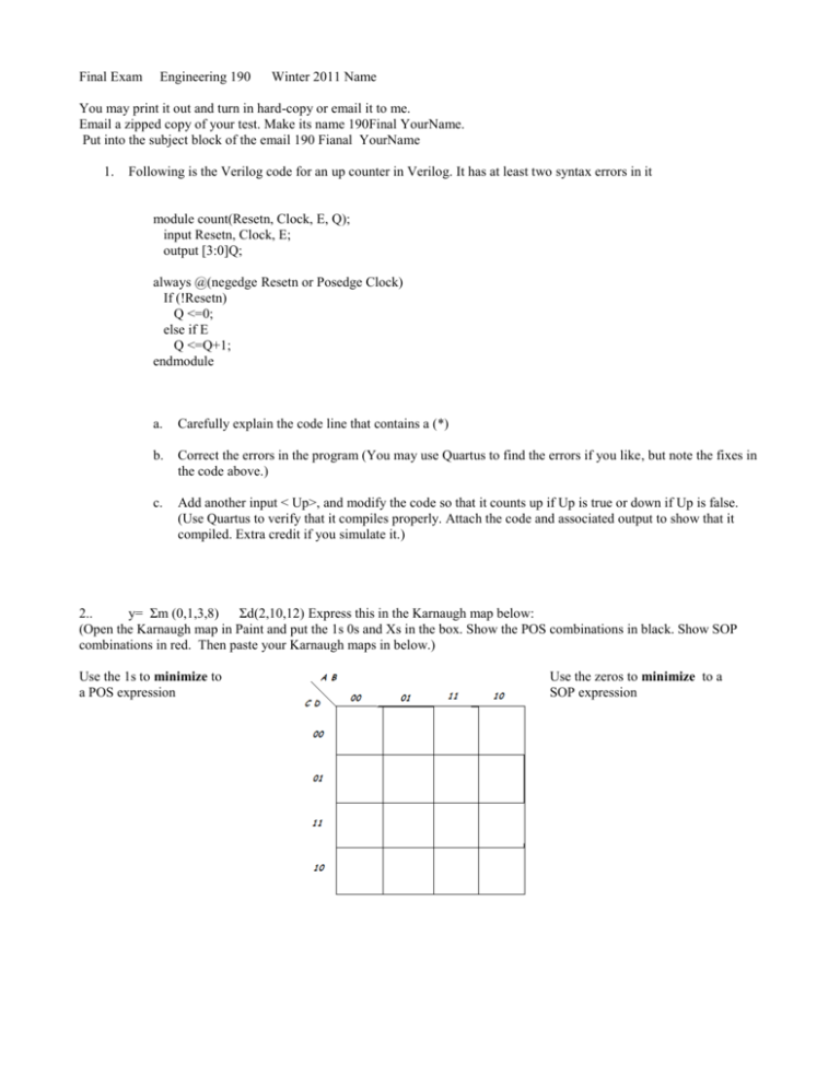
Final Exam Engineering 190 Winter 2011 Name You may print it out and turn in hard-copy or email it to me. Email a zipped copy of your test. Make its name 190Final YourName. Put into the subject block of the email 190 Fianal YourName 1. Following is the Verilog code for an up counter in Verilog. It has at least two syntax errors in it module count(Resetn, Clock, E, Q); input Resetn, Clock, E; output [3:0]Q; always @(negedge Resetn or Posedge Clock) If (!Resetn) Q <=0; else if E Q <=Q+1; endmodule a. Carefully explain the code line that contains a (*) b. Correct the errors in the program (You may use Quartus to find the errors if you like, but note the fixes in the code above.) c. Add another input < Up>, and modify the code so that it counts up if Up is true or down if Up is false. (Use Quartus to verify that it compiles properly. Attach the code and associated output to show that it compiled. Extra credit if you simulate it.) 2.. y= Σm (0,1,3,8) Σd(2,10,12) Express this in the Karnaugh map below: (Open the Karnaugh map in Paint and put the 1s 0s and Xs in the box. Show the POS combinations in black. Show SOP combinations in red. Then paste your Karnaugh maps in below.) Use the 1s to minimize to a POS expression Use the zeros to minimize to a SOP expression 4. Design a circuit that will use a 2 bit addressed MUX to implement the following truth table. Don’t simplify the expression: (Open the image in Paint and insert the notations. Paste your completed circuit in here. 5. Minimize this expression using only Boolean algebra Show your work, even if you cheat and use a Karnaugh map This will most likely best done on paper. If you do so, put your name on the paper. 6. following is a bubble state diagram describing a FSM. Create a transition table for the state diagram. Document any assumptions you make. States 0 1 2 3 4 5 A B C 7. Design a synchronous counter that counts 3,5,7,0 and repeats 8. Attached to the end of this test is a page with a PAL. Annotate everything, show your work. I give partial credit. Make it easy for me to give credit. (Open the drawing in PAINT and show connections with a red circle to show connections. Then paste it at the end of the test document.) Implement the following circuits on the PAL a. An synchronous clock that counts to five. b. Y1 = X1 X3’ t0 + X4 X2 t5 c. Y2 = X1 X2’ + X1’ X2 + B d. Y3 = t3

