Instructions
advertisement
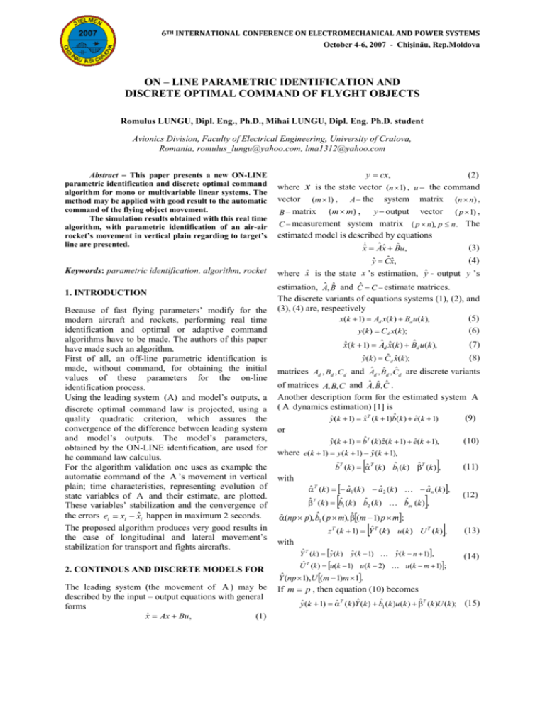
6TH INTERNATIONAL CONFERENCE ON ELECTROMECHANICAL AND POWER SYSTEMS October 4-6, 2007 - Chişinău, Rep.Moldova ON – LINE PARAMETRIC IDENTIFICATION AND DISCRETE OPTIMAL COMMAND OF FLYGHT OBJECTS Romulus LUNGU, Dipl. Eng., Ph.D., Mihai LUNGU, Dipl. Eng. Ph.D. student Avionics Division, Faculty of Electrical Engineering, University of Craiova, Romania, romulus_lungu@yahoo.com, lma1312@yahoo.com Abstract This paper presents a new ON-LINE parametric identification and discrete optimal command algorithm for mono or multivariable linear systems. The method may be applied with good result to the automatic command of the flying object movement. The simulation results obtained with this real time algorithm, with parametric identification of an air-air rocket’s movement in vertical plain regarding to target’s line are presented. y cx, where vector x is the state vector (m 1) , A the (2) (n 1) , u the command system matrix (m m) , y output vector ( p 1) , B matrix C measurement system matrix ( p n), p n . The estimated model is described by equations xˆ Aˆ xˆ Bˆ u, (3) yˆ Cˆ xˆ, Keywords: parametric identification, algorithm, rocket 1. INTRODUCTION Because of fast flying parameters’ modify for the modern aircraft and rockets, performing real time identification and optimal or adaptive command algorithms have to be made. The authors of this paper have made such an algorithm. First of all, an off-line parametric identification is made, without command, for obtaining the initial values of these parameters for the on-line identification process. Using the leading system (A) and model’s outputs, a discrete optimal command law is projected, using a quality quadratic criterion, which assures the convergence of the difference between leading system and model’s outputs. The model’s parameters, obtained by the ON-LINE identification, are used for he command law calculus. For the algorithm validation one uses as example the automatic command of the A ’s movement in vertical plain; time characteristics, representing evolution of state variables of A and their estimate, are plotted. These variables’ stabilization and the convergence of the errors ei xi xˆi happen in maximum 2 seconds. The proposed algorithm produces very good results in the case of longitudinal and lateral movement’s stabilization for transport and fights aircrafts. ( n n) , (4) where x̂ is the state x ’s estimation, ŷ - output y ’s estimation, Aˆ , Bˆ and Ĉ C estimate matrices. The discrete variants of equations systems (1), (2), and (3), (4) are, respectively (5) x(k 1) Ad x(k ) Bd u(k ), (6) y(k ) Cd x(k ); xˆ (k 1) Aˆ d xˆ (k ) Bˆ d u (k ), (7) yˆ (k ) Cˆ d xˆ (k ); (8) matrices Ad , Bd , Cd and Aˆ d , Bˆ d , Cˆ d are discrete variants of matrices A, B, C and Aˆ , Bˆ , Cˆ . Another description form for the estimated system A ( A dynamics estimation) [1] is (9) yˆ (k 1) xˆ T (k 1)bˆ(k ) eˆ(k 1) or (10) yˆ (k 1) bˆT (k ) zˆ(k 1) eˆ(k 1), where e(k 1) y(k 1) yˆ (k 1), bˆT (k ) ˆ T (k ) bˆ1 (k ) ˆ T (k ) , with (11) ˆ T (k ) aˆ1 (k ) aˆ 2 (k ) aˆ n (k ), ˆ T (k ) bˆ1 (k ) bˆ2 (k ) bˆm (k ) , ˆ (np p), bˆ1 ( p m), ˆ (m 1) p m; z T (k 1) Yˆ T (k ) u(k ) U T (k ) , with Yˆ T (k ) yˆ (k ) yˆ (k 1) yˆ (k n 1), Uˆ T (k ) u (k 1) u (k 2) u (k m 1); 2. CONTINOUS AND DISCRETE MODELS FOR Yˆ (np 1),U (m 1)m 1. The leading system (the movement of A ) may be described by the input – output equations with general forms x Ax Bu, (1) If m p , then equation (10) becomes (12) (13) (14) yˆ (k 1) ˆ T (k )Yˆ (k ) bˆ1 (k )u (k ) ˆ T (k )U (k ); (15) if m p , then ˆ T (k ) matrix can not be multiplied wit U (k ) vector because of their dimensions. That’s why, in equation (15) the last term is expressed for each concrete case (function of m and p values). So that, in the case presented below (rocket’s movement in vertical plain) n 4, m 1 and equation (15) becomes yˆ (k 1) ˆ T (k )Yˆ (k ) bˆ1 (k )u(k ), where Yˆ T (k ) yˆ (k ) yˆ (k 1) yˆ (k 2) yˆ (k 3), ˆ T (k ) aˆ1 (k ) aˆ2 (k ) aˆ3 (k ) aˆ4 (k ), (16) (17) b̂1 is a ( p 1) vector, ŷ is a ( p 1) vector and u(k ) (1 1) . For command law u (k ) obtaining, one chooses the performance indicator T J y(k 1) yˆ (k 1) Qy(k 1) yˆ (k 1) uT (k ) Ru(k ), (18) where y (k 1) is the imposed output vector while Q( p p) and R(m m) are symmetric and positive definite matrices, R nonsingular matrix; y (k 1) has the form (17). The optimal command is obtained from optimum condition J 0 , u ( k ) ˆ T (k )Yˆ (k ) , u(k ) G y(k 1) for m 1; G has the expression 1 G R bˆ1T (k )Qbˆ1 (k ) bˆ1T (k )Q. algorithm in rapport with Âd and B̂d matrices and after that the matrix Q C T QC is calculated. G matrix from (20) is obtained with b̂1 extracted from bˆ(k ). Then command u(k ) is computed with (19). The vectors x(k 1) , xˆ (k 1) , y (k 1) and yˆ (k 1) are calculated; vectors Yˆ (k 1) and U (k 1) are memorized and the error eˆ(k 1) y(k 1) yˆ (k 1) is computed. The actualization of covariance matrix is made with formula [1] zˆ(k 1) zˆ T (k 1) P(k 1) P(k ) I mn P(k ) (21) T ˆ ˆ z ( k 1 ) P ( k ) z ( k 1 ) and, with this, bˆ(k 1) bˆ(k ) P(k 1) zˆ(k 1)eˆ(k 1), (22) where zˆ(k 1) has the form (13). State variables xi (t ) and xˆi (t ) are plotted. 4. IDENTIFICATION AND OPTIMAL COMMAND OF THE ROCKET’S MOVEMENT (19) (20) Q and R matrices may be calculated using ALGLX algorithm proposed by the authors of this paper or other algorithms [3], [4], [5]. 3. A ’S PARAMETERS IDENTIFICATION First of all the off – line system A ’s parameters identification is made, using, for example, the least square method (LSM), resulting the parameters vector bˆ0 bˆ(0) ; in this moment the system’s command is uncoupled, therefore the system is an open loop one. yˆ (t ) is then computed and the vectors For the identification and discrete optimal command algorithm’s validation, present above, a simulation program was made in the MATLAB medium. Considering model of A ’s movement in rapport with equal signal line [6], [7], with state vector x T y y , u ; y and y are lateral deviation and lateral deviation angular velocity, respectively, - incidence angle variation, pitch angular velocity . With flying parameters’ values from [8], for the 40 th second of flight, following step by step the algorithm, one obtained successively the results b0T 4.02 - 6.06 4.05 - 1.01 - 10-3 0.04 - 10-3 0.46 - 10-3 0.46 - 10-3 0.04 bˆ0T 3.84 - 5.50 3.46 4.023 - 6.062 Ad 4.053 - 1.015 Yˆ0 Yˆ (0) and U 0 U (0) are memorized. Also, the covariance matrix P0 is memorized at the end of identification P0 P(0) . Then, matrices Ad , Bd , Aˆ d , Bˆ d are computed and with these state vectors x and x̂ are computed; these vectors (at the end of identification) are memorized. For simulation of time varying of A ’s parameters, the parameters of A are modified (for example with 5%) and with the new coefficients Ad and Bd matrices are computed. The loop is then closed (one adds u (k ) command) and Q and R matrices are computed with ALGLX - 0.81 - 0.006 0.06 0.13 - 0.05 1 0 0 3.845 - 5.503 0 1 0 ˆ ; Ad 3.469 0 0 1 0 0 0 - 0.811 1 0 0 0 1 0 ; 0 0 1 0 0 0 B d 10 3 0.041 0.461 0.462 0.042 ; C d 1 0 0 0; D d 0 Bˆ d - 0.0064 0.0612 0.1361 Cˆ d 1 0 0 0; Dˆ d 0 T - 0.0564 ; T and b vector of the system with optimal command bT 3.82 - 5.75 3.85 - 0.96 - 3.9710-5 - 0.4310-3 Also one obtained Q 0.1067, R 1 . - 0.4310-3 - 4 10-5 In fig.1 state variables xi (t ), xˆi (t ) and (t ) are presented ( xi (t ) with blue and xˆi (t ) with red). Fig.1 – Time varying of xi , xˆi and 5. CONCLUSIONS The paper presents an ON – LINE parametric identification and discrete optimal command algorithm for linear systems. For validation, it is used to automatic command of a rocket’s movement in vertical plain with respect to equal signal line, which materializes target line. A simulation program based to presented algorithm was made in Matlab/Simulink. The obtained graphic plots express time evolution of the state variables xi (t ), xˆi (t ) and the evolution of command (t ) . References [1] P. Eykhoff, Identificarea sistemelor. Editura Tehnica, Bucuresti, 1977. [2] Mc. Donald, Automatic Flight Control Systems. New York–London–Sydney–Tokyo-Singapore, 1990. [3] L. Ljung, J. Sjoberg, H. Hjalmarsson, Identification, Adaptation, Learning –The Science of Learning Models from Data, Edited by S. Bittoni, Springer Verloy Berlin Heideberg, 1996. [4] J.W. Choi, A Simultaneous Assignment Methodology of Right/Left Eigenstructures. IEEE Transactions on Aerospace and Electronic Systems, 1998, pag. 625 – 634. [5] J.W. Choi, LQR Design with Eigenstructure Assignment Capability. IEEE Transactions on Aerospace and Electronic Systems, vol. 35, Nr. 2, April, 1999, pag. 700 – 707. [6] R. Lungu, Sisteme de dirijare aerospatiala. Editura Sitech, Craiova, 2002. [7] M. Lungu, Calculul vitezelor de apropiere si deviatie de la linia tintei. The International Symposium on Naval and Masine Education. Vav – MAR – EDU 2001, Section Military Scienece, pag. 113-119 in Procedings, Constanta, May 2426, 2001. [8] I. Aron, R. Lungu, Automate de stabilizare si dirijare. Editura Militara, Bucuresti, 1991.
