TRAVERSE ANGLE, AZIMUTH, and DISTANCE MEASUREMENT
advertisement
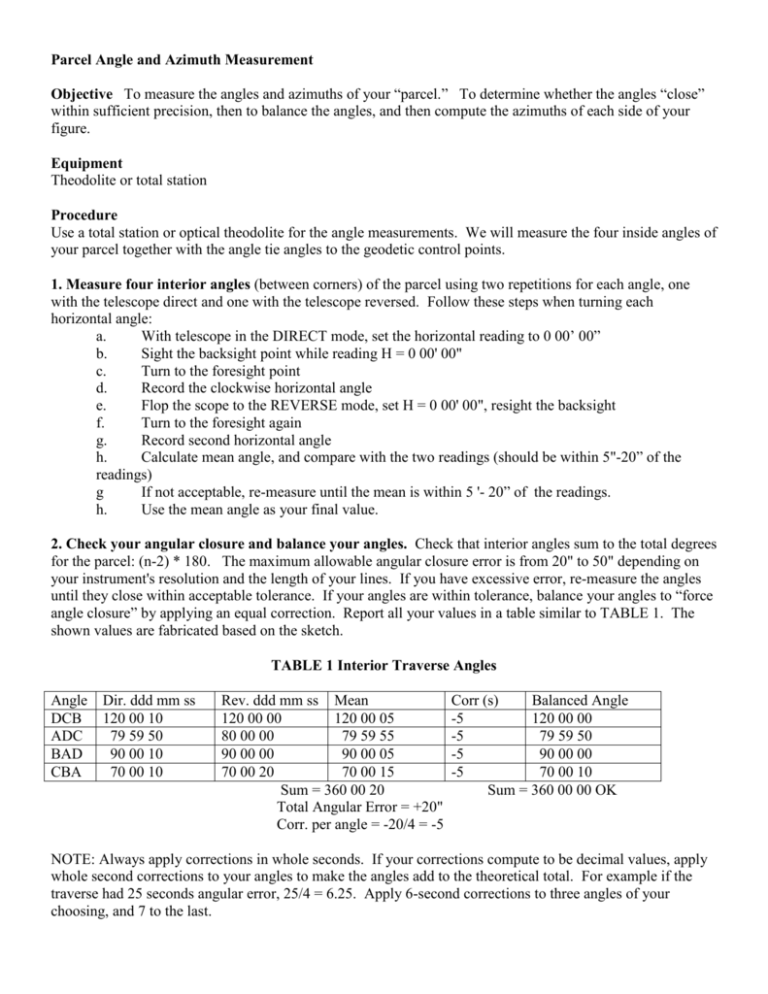
Parcel Angle and Azimuth Measurement Objective To measure the angles and azimuths of your “parcel.” To determine whether the angles “close” within sufficient precision, then to balance the angles, and then compute the azimuths of each side of your figure. Equipment Theodolite or total station Procedure Use a total station or optical theodolite for the angle measurements. We will measure the four inside angles of your parcel together with the angle tie angles to the geodetic control points. 1. Measure four interior angles (between corners) of the parcel using two repetitions for each angle, one with the telescope direct and one with the telescope reversed. Follow these steps when turning each horizontal angle: a. With telescope in the DIRECT mode, set the horizontal reading to 0 00’ 00” b. Sight the backsight point while reading H = 0 00' 00" c. Turn to the foresight point d. Record the clockwise horizontal angle e. Flop the scope to the REVERSE mode, set H = 0 00' 00", resight the backsight f. Turn to the foresight again g. Record second horizontal angle h. Calculate mean angle, and compare with the two readings (should be within 5"-20” of the readings) g If not acceptable, re-measure until the mean is within 5 '- 20” of the readings. h. Use the mean angle as your final value. 2. Check your angular closure and balance your angles. Check that interior angles sum to the total degrees for the parcel: (n-2) * 180. The maximum allowable angular closure error is from 20" to 50" depending on your instrument's resolution and the length of your lines. If you have excessive error, re-measure the angles until they close within acceptable tolerance. If your angles are within tolerance, balance your angles to “force angle closure” by applying an equal correction. Report all your values in a table similar to TABLE 1. The shown values are fabricated based on the sketch. TABLE 1 Interior Traverse Angles Angle DCB ADC BAD CBA Dir. ddd mm ss 120 00 10 79 59 50 90 00 10 70 00 10 Rev. ddd mm ss Mean 120 00 00 120 00 05 80 00 00 79 59 55 90 00 00 90 00 05 70 00 20 70 00 15 Sum = 360 00 20 Total Angular Error = +20" Corr. per angle = -20/4 = -5 Corr (s) Balanced Angle -5 120 00 00 -5 79 59 50 -5 90 00 00 -5 70 00 10 Sum = 360 00 00 OK NOTE: Always apply corrections in whole seconds. If your corrections compute to be decimal values, apply whole second corrections to your angles to make the angles add to the theoretical total. For example if the traverse had 25 seconds angular error, 25/4 = 6.25. Apply 6-second corrections to three angles of your choosing, and 7 to the last. 3. Measure two "geo-referencing" angles – (1) From your "Base Control Point" geodetic station, sight your "Backsight Control Point" and turn the clockwise angle to your nearest parcel corner (we'll call this the "reference corner" of your parcel.) Turn this angle twice and take the mean. (2) Set up on the "reference corner", backsight the "Base Control Point" geodetic station and turn the angle to the first station in your traverse. This line is termed the "reference side". Double the angle and take the mean. Sample Layout Base Control Point (X) (3280455.143 North 369611.580 East) State Plane Coord. #1 B Reference Side #2 Reference Corner C Backsight Control Point (Y) (3280406.858 North, 369683.047 East) State Plane Coord Parcel A D 4. Calculate the Azimuths of your Parcel Sides – a. CALCULATION 1: Determine the “control azimuth” – the direction from your “base control point (X)” to the “backsight control point (Y).” If the azimuth is published, do the following calculation to check it. If you only know the State Plane Coordinates coordinates, you must calculate the control azimuth by “inversing” between known coordinates: Azimuth = arc tan((Easting of Y – Easting of X)/(Northing of Y – Northing of X)) arc tan((683.047-455.143)/(406.858-455.143)) arc tan(-4.719975) = -78.03788 +180 = 101.9621 = 101 57 43 dms NOTE: If the arc tan comes out negative, add 180 (or 360) to put the azimuth in the correct quadrant. b. CALCULATION 2: Calculate the azimuth of your parcel’s “reference side” by applying your two measured georeferencing angles to the control azimuth. Use the relation ship that if the angle ABC is between three points where A is the backsight, B is the vertex, and C is the foresight: Azimuth of BC = Azimuth of BA + clockwise angle ABC Using YXC = 90 00 00 and XCB = 260 00 00 for the two georeferencing angles, gives the following calculation. Calculating the Traverse Reference Azimuth Azimuth XY 101 57 43 +YXC 90 00 00 Azimuth XC 191 57 43 -180 -180 00 00 Back Azimuth CX 11 57 43 +XCB 260 00 00 Azimuth CB 271 57 43 NOTE: Get back azimuth by adding or subtracting 180. If an azimuth exceeds 360, subtract off the 360. c. CALCULATION 3 – Calculate your traverse azimuths by applying your measured interior angles to the reference azimuth. Use the same method as above: Calculating the Traverse Azimuths Azimuth CB 271 57 43 -180 +/-180 Back Azimuth BC 91 57 43 +CBA + 70 00 10 Azimuth BA 161 57 53 +180 +/-180 Back Azimuth AB 341 57 53 +BAD + 90 00 00 Azimuth AD 431 57 53 -360 - 360 Azimuth AD 71 57 58 +180 +/-180 Azimuth DA 251 57 53 +ADC + 79 59 50 Azimuth DC 331 57 43 -180 +/-180 Back Azimuth CD 151 57 43 +DCB +120 00 00 Azimuth CB 271 57 43 Check!! NOTE: By going around the traverse applying all four clockwise angles which add to 360 themselves, we recalculate the parcel’s reference azimuth. We did and it checked! Submit: An MS Word document explaining your methods and results including a table of your angles and computations. You may put make the table in Excel and copy and paste it into your Word document.


