Lecture notes set #11 (powerpoint, summary of slides shown over
advertisement

Photon Echo Technique
Quantum Mechanics of Ensembles
Described by the density matrix rather than a wavefunction.
=
P
Two level system
eg
= c1eiE1t /
1
1 =
0
1 + c2 e iE2t /
0
2 =
1
c12
=
i ( E1 E2 ) t /
c1c2 e
=
2
c1c2 ei ( E1 E2 ) t /
c22
11 12
21 22
The evolution of the electric field is governed by the polarization P.
P = N < > = N x Tr ( )
couples the two states i.e.
aa bb = 0, ab = ba =
P = N ( ba ab )
Calculating Nonlinear Signals
Time evolution of
used to calculate the polarization P
1
[H, ]
t i
Expand P as P = <P (1) > + <P (2) + <P (3) .........
with <P (n) = Tr ( (n) P)
2 ( j k )
8 terms
(3) ( j,k , )
48 terms
Long and tedious expressions.
Help is at hand!
For a two level system only 4 terms and their complex conjugates survive
the definition of the density matrix
=
Suggests we can represent these terms by diagrams in which we propagate
the bra and ket separately.
Feynman diagrams & the density matrix
phase-matching direction
energy
|e
ks = -k1+k2+k3
k3
k2
|g
k1
time
ks
t
density matrix
|g g|
g|
|e g|
k3
|e e|
T
t
k2
|g e|
|g g|
-k1
1
|g
|e
e|
-k1
d0
ks
k2
0d
k3
d0
Two level systems are described by four Feynman
diagrams and their complex conjugates
ks
ks
k3
k3
Geg(t3)
Geg(t3)
Gee(t2)
Gee(t2)
Geg(t1)
k1
g
R1
k2
k2
R2
g
ks
ks
Geg(t3)
k3
Gge(t1)
Ggg(t2)
Geg(t3)
k2
k3
k2
Gge(t1)
k1
R3
If k3 = k2 (same pulse)
Ggg(t2)
Geg(t1)
k1
ks= k1 for R1 and R4
ks = 2k2-k1 for R2 and R3
R4
k1
Echo-Inhomogeneous broadening
from Erwin Hahn and Chris Noble
Lens Analogy for Photon Echoes
After the first interaction we have a superposition
oscillating at the energy difference between
g and e .
t
i eg t1
dtd eg (t )
0
e
Optical
frequency
(1)
Homogeneous
dephasing
(2)
e
(3) Define electronic phase factor
i
t1 (t1 )
e
i t1
Inhomogeneous
contribution
leads to rephasing
(3)
Linear with slope determined by
inhomogeneous parameter
For N molecules we get N lines with different slopes
Width amount of inhomogeneity
The second interaction produces a population—no ε-term in
difference between |e> and |e>
Rephasing
response
function
Now the third pulse e g phase
factor is ei t3 (sign change because
now Ee-Eg not Eg-Ee), so now the slope
of each ray will change sign but
have the same magnitude.
Non-rephasing response function
2 PE
t1
t2
Dephasing
Spectral diffusion
Dephasing
Refocusing gets poorer
and poorer as t1, t2
increased.
t1
t2
t3
Photon Echoes
1
2
3
echo
Pulse 2 creates population
(|g> OR |e>)
Pulse 1 creates coherence
Pulse 3 creates another
(|g> AND |e>)
coherence
Oscillatory term during first (second) coherence: e -(+)iωegt
Slope of rays depends on ωeg in oscillator term
Top: CO asymmetric stretch of W(CO)6 in 2 methyl pentane.
Bottom: CO asymmetric stretch of W(W)6 in dibutyl phthalate.
The beats are at the anharmonic vibrational splitting, and arise
because the pulsewidth (0.7ps) is less than in the top figure.
Figure 3. Temperature
dependence of the
homogeneous line widths
of the T|u CO stretching
mode of W(CO)6 in 2MTHF, 2-MP, and DBP
determined from infrared
photon echo experiments
using eq 9b.arrows mark
the glass transition
temperatures. Note the
different temperature and
line width scales.
W(CO)6 in 2-MP
Tokmakoff….Fayer J. Phys. Chem, 99 13310 (1995).
Absorption Linewidth
Two Pulse Electronic Echoes
2k1-k2
2k2-k1
HITCI in
glycerol/water
(70/30)
20 fs transform
limited pulses
Deconvolution
20 fs decay
Exciton Dephasing in Semiconducting Carbon Nanotubes
Diffracted Signal (arb. units)
Normalized Absorbance a.u.
1.0
~0.75 nm
1.0
77 K
RT
AC
0.5
(6, 5) E11 SWNT Peak
Homogeneous
contribution
0.5
0.0
900
950
1000
1050
1100
Wavelength (nm)
• Only the (6,5) type SWNTs are resonantly
excited, and the resulting 2-pulse photon
echoes (2PEs) decays are measured
• 2PEs provides a direct method to
determine dephasing times
0.0
-200
0
200
Time Delay t (fs)
400
• At RT, the FWHM of the inhomogeneous
processes are ~6X the homogeneous width
2D Spectroscopy of Aggregates
MOLECULAR AGGREGATES
WEAKLY COUPLED
STRONGLY COUPLED
Absorption spectra of BIC monomer
and J-aggregates
LH2 Complex
Two-exciton
Band 2e
Linear chain of 2 level
molecules with electrostatic
dipole-dipole interaction
One-exciton
Band 1e
Ground state g
J-AGGREGATE HAMILTONIAN
SITE BASIS:
N
H (q) n n n
n 1
N
m
m ,n 1
m n
Off-diagonal
Electrostatic
N
ph
el ph
J mn n n H nn
( q) n H (q)
n 1
Diagonal
Electron-Phonon
EXCITON BASIS:
Diagonal Exciton-Phonon Off-Diagonal Exciton-Phonon
Renormalization Factors
Cause Exchange Narrowing
Overlap Factors Define
Relaxation
•Higher Exciton States are Strongly Delocalized
•Exchange-Narrowing is Stronger for Higher
(More Delocalized) Exciton States
•Relaxation is Faster for Higher Exciton States
EXCITON WAVEFUNCTIONS
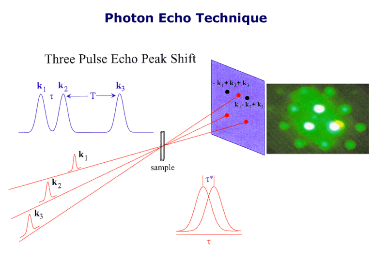
Photon Echo Technique
Integrated Three Pulse Photon Echo:
Nile Blue in Acetonitrile
Origin of the Peak Shift
Non-rephasing side
not influenced by
spectral diffusion
Rephasing side as spectral
diffusion occurs will become
more and more like nonrephasing side
Eventually the echo signal will become symmetric around τ=0
Measuring inhomogenous broadening
200
Peakshift tracks the surface denoted
by the blue line
30
100
25
20
Peakshift, (fs)
Population Time, T (fs)
150
15
50
10
5
0 0
200
400
600
800
Population Time, T (fs)
0
-20
0
20
Coherence Time, t (fs)
40
60
IR 144 τ*(T) vs. T
• Finite long
time peak shift
• Inhomogeneous
broadening
32K
294K
Ethanol 294K
• Timescales of
fluctuations in
transition frequency.
What is the Peak Shift?
At high temperature it relates to the Stokes shift dynamics (S (t ) M (t))
and the ratio of dynamical and static contributions to the spectral
broadening.
*
The long time value (t (T )) allows the inhomogeneous width to
obtained: in
( )
The time dependence gives S (t)
Stokes Shift
t *(T )
2
2in
f (t )(S (T ) in2
[( 2in2 f (T )) 2in2 f (T )]
2 /
t (T )
*
M. Cho
inhomogeneous
width
2
in2 in2 ( / )2
[( 2in2 ( / )2 ) 2in2 ( / )2
obtain
inhomogeneous
width, in
Solvation Dynamics IR144 in acetonitrile
Correlation function
Peak Shift
Spectral Density
Instantaneous Normal Mode Spectral Density
CH3CN
Solvation Spectral Density for Acetonitrile
Dielectric Response of Aqueous Proteins
Lysozyme with eosin bound in the ‘hydrophobic box’
Eosin/lysozyme/water
Eosin/water
Model spectral densities
Dielectric continuum models
500
cm-1)
400
300
200
100
0
10-3
10-2
10-1
100
101
102
103
c (cm-1)
bulk water, static lysozyme
bulk water, static lysozyme , bound water
bulk water, bound water dynamic lysozyme
bulk water, dynamic lysozyme from MD
LH1 and Reaction Center of Purple Bacteria
Roszak, Howard, Southhall,
Gardiner, Law, Isaacs & Cogdell
Science, 302, 1969 (2003).
Structure of the LH3 Complex
Rhodopseudomonas acidophila Strain 7050
K. McLuskey et al.: Biochemistry
40, 8713 (2001).
Photon Echo Peak Shift Measurements
Peak Shift (fs)
LH1 of Rb. sphaeroides vs. the B820 Subunit of LH1 of Rs. rubrum
Same parameters as LH1
except no 90 fs EET
component
B820 subunit of LH1
Inhomogeneous broadening
90 fs energy transfer
timescale
LH1
T(fs)
Absorbance (norm.)
Light Harvesting Complex II
Wavelength/nm
Bacterial Light Harvesting
Bahatyrova, et al.
Nature (2004) 430 1058
Hu, et al.
J. Phys. Chem. B (1997) 101 3854
Peak Shift on the B850 band of
LH2 membranes (Rps. acidophila)
20
15
Intra-complex exciton
relaxation or energy transfer
Peak Shift, fs
Peak Shift, fs
20
15
10
Membrane samples
5
Solubilized samples
0
10
100
1000
10000
Population Period, fs
Energy Transfer between the complexes
5
In collaboration
with C. N. Hunter,
Sheffield
Membrane samples
0
Solubilized samples
0
2000
4000
6000
8000
10000
Population Period, fs
Since the Peak Shift carries information abut the inter-complex energy transfer
dynamics, we can say that the individual rings do not have the full disorder
distribution that is observed in the absorption spectrum. Energy Transfer between
the rings is estimated to be ~ 5 ps at room temperature.
Pump Probe (Transient Absorption)
IR144 in MeOH
Pump-Probe (Transient Absorption)
k1and k2 come from same pulse
ks
gg
k3
ks = -k1 + k1 + k3 = k3
signal along probe direction
eg
ee
k2
P(3) heterodyned with probe field.
ge
gg
k1
rephasing diagram
Measurement time window (t’) determined by the
pulse duration of the probe.
• If the probe is short rephasing may not be
detected.
• M(t) reflected in pump-probe signal
(may be difficult to extract quantitatively).
• “coherence” spike not a coherent effect.
Arises from dynamics.
Contributions to Pump-Probe Signal
Pump Probe Signals (Calculation)
Transient Absorption
Coworkers
Taiha Joo
Minhaeng Cho
Yutaka Nagasawa
Sean Passino
Matt Lang
Xanthipe Jordanides
Xeuyu Song
Peak Shift IR144 in MeOH
1-Color Transient Grating Signals
1.1
(a)
1-C TG Signal (normalized)
1.0
0.9
= 100, 200, 300, 400, 500 fs
0.8
(from left to right)
0.7
0.6
2 / ) 0 5exp(2t )]
[exp(
t
S (t )
0.5
15
0.4
0.3
0.0
0.2
0.4
0.6
0.8
1.0
Time (ps)
Time unit: ps.
(b)
1-C TG Signal (normalized)
1.0
0.8
600cm1
0.6
Total 1-C TG signal
= 100 fs
0.4
2
0.2
Transient dichroim (Im[P] )
2
Transient birefringence (Re[P] )
0.0
0.0
0.2
0.4
0.6
Time (ps)
0.8
1.0
Two Color Transient Grating Signals
2-C TG Signal (arbitrary unit)
16
(a)
14
12
W = 0, 200, 400, 600, 800, 1000, 1200, 1400 cm
(from top to bottom)
10
[exp(t 2 / ) 0 5exp(2t )]
S (t )
1 5
8
600cm1
6
4
W pump probe
2
0.0
0.2
0.4
0.6
0.8
1.0
Time (ps)
(b)
2-C TG Signal (arbitrary unit)
-1
8
Total 2-C TG signal
-1
2
4
Transient dichroim (Im[P] )
2
2
Transient birefringence (Re[P] )
0
0.0
0.2
0.4
0.6
Time (ps)
0.8
Negative
W 'uphill'
At W 1200cm ( 2)
the probe is at the bottom
of the excited state well.
1
= 100 fs
W = 800 cm
6
Positive W 'downhill'
1.0
For large detuning the birefringent
contribution becomes similar to the
dichroic contribution (at short times).
Two Color Transient Grating Signals.
Homodyne Detection
2-C TG Signal (arbitrary unit)
9
= 100, 200, 300, 400, 500 fs
Detuning = 800cm-1
(from left to right)
8
7
[exp(t 2 / ) 0 5(exp 2t )]
S (t )
1 5
6
5
4
0.0
0.2
0.4
0.6
Time (ps)
0.8
1.0
Maximum correlates well
with Gaussian time
constant, .
Experimental 1-Color and 2-Color TG
Signals for DTTCI in MEOH
Normalized Intensity
1
0.9
0.8
0.7
0.6
800, 800, 800
0.5
0.4
0.3
0.2
750, 750, 750
800, 800, 750
750, 750, 800
0.1
0
-50
150
350
550
750
950
Population Time (fs)
Downhill. Detuning = 833cm1 , 430cm1
Probe close to minimum of excited state surface.
Experimental One-Color and 2-Color TG
Signals for IR144 in MEOH
1C 750nm
2C 750, 750 800nm
Normalized Intensity
1.0
0.5
0.0
1
10
100
1000
10000
Population Time, fs
1500cm1
W 833cm1 (downhill)
Two-Color three-pulse Photon Echoes
1
Intensity (normalized)
IR144 in Methanol
0.8
0.6
0.4
0.2
0
600
650
700
750
800
850
900
800
850
900
Wavelength (nm)
Intensity (normalized)
1
DTTCI in Methanol
0.8
0.6
0.4
0.2
0
600
650
700
750
Wavelength (nm)
IR144 Methanol 750, 750, 800
P e a k s h i f t (f s)
15
10
5
0
-5
0
100
200
300
P o p u l a t i o n T i m e (fs)
Type I
Type II
Difference
400
500
Difference Peak Shift
For a fixed phase matching direction, i.e., k3 + k2 – k1
k
k3
eg
k2
s
eg
ee
TI
TII
ee
ge
τI
τII
eg
gg
k1
k1
gg
k2
Type I scan
Echo (Rephasing)
(pulse sequence, 1-2-3)
k3
Type II scan
FID (Non-Rephasing)
(pulse sequence, 2-1-3)
Difference peak Shift = Type I - Type II
20
Two Colour
15
Peak Shift, fs
Difference Peak Shift, fs
7
10
5
Type I
0
Type II
-5
0
200
400
600
800
Population Period, fs
1000
Δτ*(T) = τI*(TI) - τII*(TII)
6
5
4
3
2
1
0
0
200
400
600
800
Population period, fs
1000
IR144 Methanol 750, 750, 800
P e a k s h i f t (f s)
15
10
5
0
-5
0
100
200
300
P o p u l a t i o n T i m e (fs)
Type I
Type II
Difference
400
500
Experimental Difference Peak Shift Data (downhill)
Pulse Sequence, 750-750-800 nm
t Difference Peak Shift, fs)
5
IR144 in Methanol
4
3
2
1
DTTCI in Methanol
0
10
100
1000
10000
Population Period, fs
The Difference Peak Shift starts at a near zero value, then rises to a maximum value in ~ 200 fs
and then decays to zero for both IR144 and DTTCI in methanol
Based on the turnover time, it is suggested that the ultrafast component in methanol is ~ 200 fs
Spectral Models and the Two-Color Difference Peak Shift
Downhill Case
8
1
0.9
I
0.7
0.6
0.5
0.4
0.3
0.2
0.1
0
-1000
-500
0
500
1000
1500
1
0.9
0.8
II
0.7
0.6
2 modes.
0.5
0.4
0.3
0.2
0.1
0
-1000
-500
0
500
1000
1500
1
0.9
0.8
III
0.7
35 modes.
0.6
Difference Peak Shift, t, fs
1 mode.
Gaussian
M(t)
0.8
I
6
II
II
4
III
2
0.5
0.4
0
0.3
0.2
0.1
0
-1000
-500
0
500
0
1000
200
400
600
1500
Population Period, fs
800
1000
Two-Color 3PEPS as a Probe of Memory Transfer in
Spectral Shift
Transition Density
Time-Dependent Spectral Shift
probe pump
Randomized Shift
Memory-Conserved Shift
=
+
Energy
Two-Color 3PEPS measures correlation dynamics
(between transition energies in pumped and probed regions).
:
depr (t )depu
Homogeneous and Inhomogeneous Distributions
of Transition Energies
•
•
Homogeneous distribution
s hom ( w; j g ) =
å d (w - (E j
j
e
- Ej g
e
A particular nuclear state
in the ground electronic state
))
je j
2
g
Inhomogeneous distribution
s ( w) =
å
j
s hom ( w; j g )Pg (j g )
g
Statistical probability for a molecule to occupy
the nuclear state j g
Two Mechanisms for Existence of Non-Linear Signals of Two-Color Experiments
•
Interactions of pump and probe lasers have to be made with the same
molecule
A) Spectral Overlap due to
Homogeneous Distribution
•
B) Spectral evolution due to
Fluctuation of Inhomogeneous Distribution
These two mechanisms are included in the response function
formalism in a complicated way
A Simple ad hoc Model for the Dynamics of Correlation
Function
Total Signal = Phom (t )R hom (t ) + Pinhom (t )R inhom (t )
Total Correlation Function
depr (t )depu =
Phom (t )
Phom (t ) + Pinhom (t )
depr (t )depu
hom
At short times, Phom (t ) > > Pinhom (t )
+
Pinhom (t )
Phom (t ) + Pinhom (t )
depr (t )depu
inhom
At longer times, Phom (t ) < < Pinhom (t )
Inhomogeneous distribution fluctuates with time due to random fluctuation of the statistical distribution of the
nuclear states, which is described by a stochastic approach.
depr (t )depu
P( 2 ; t | 1 )
inhom
=
1
d w d w w - w(t )
N (t ) ò ò 1 2 2
(
pr
)(w 1
w
pu
)W (w2 E pr )P (w2 ;t
[( 2 ) (1 ) M (t )]2
exp
2
2
2 (1 M (t ) )
2 2 (1 M (t ) 2 )
1
w1 )W (w1 E pu )s abs ( w1 )
P(2 ;0 | 1 ) d (2 1 )
Skinner et al, J. Chem. Phys. 106, 2129 (1997)
Dynamics of Conditional Probability for the
Inhomogeneous Distribution
inhom
Full Response Function
0
100
200
300 400
Time (fs)
500
Rephasing Capability
Normalized Difference Peak Shift
depr (t )depu
600
Homogeneous broadening domain
: No common transitions between the pump and the probe
(no rephasing capability)
Rise in Two-Color Difference Peak Shift ~ Inertial Solvation Dynamics
Uphill and Downhill difference peak shifts should have distinct behavior for systems
with a systematic red shift
t(T), Difference Peak Shift, fs
Model Calculations for Difference Peak Shift
(downhill)
10
Difference Peak Shift = TypeI - Type II
8
6
M (T ) exp[(t /t g )]2
500
300
4
200
100
2
0
50
-2
0
200
400
600
800
1000
Population Period, fs
Empirical formula:
tg
T turnover ~ t g{c1log(c2 / ) c3},
Gaussian Time Constant, reorganization energy
Frequency difference between the two pulses
Adding exponentials and vibrations does not alter the turnover time significantly.
Therefore, we can extract information of the Gaussian parameters from the
turnover time.
Simulation model for the Difference Peak Shift
Pulse Sequence: 750-750-800 nm
5
IR144 in Methanol
3
5
4
Difference Peak Shift
Difference Peak shift, fs
4
2
1
3
2
1
0
0
1000
2000
3000
4000
5000
800
900
Population Period, fs
0
0
100
200
300
400
500
600
700
1000
Population Period, fs
Simulation scheme: Type I and II peak shifts were calculated using a
Gaussian (220 fs, = 150 cm-1) ,exponential 1 (2500 fs, = 75 cm-1),
exponential 2 (9500 fs, 70 cm-1), 35 intramolecular modes ( tot ~ 400 cm-1)
Two Color Peak Shift: Energy Transfer Systems
Difference Peak Shift
Type I (rephasing)
Type II (nonrephasing)
In an inhomogeneous energy transfer system, spectral
overlap induces correlation between donors and acceptors.
1-and 2-Color (620, 620, 700nm) Photon
Echo Peak Shift
• 1-color and 2-color
peakshifts of LuPc2 are
very similar
30
LuPc 2
1-color
• Oscillation, of similar
period in both
measurements, but
approximately π out of
phase
Peakshift (fs)
20
2-color
10
0
0
100
200
300
Population Time (fs)
400
500
Theory for 2C3PEPS of Excitonically
Coupled Molecules
• εA, εB = site energies
2J
tan( 2) eq eq
A B
C C 2 sin 2 cos 2
• J = coupling
• θ = degree of mixing
• Cμν = theoretical renormalization
coefficient for line broadening
function
ttwo (T )
• Ct* = experimentally determined
C C * (T )
t
renormalization coefficient for line
ttwo (T ) tone (T )
broadening function ratio.


