AER710SpacePropulsion6
advertisement
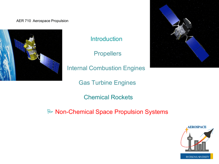
AER 710 Aerospace Propulsion Introduction Propellers Internal Combustion Engines Gas Turbine Engines Chemical Rockets Non-Chemical Space Propulsion Systems Introduction to Non-Chemical Space Propulsion Systems • The chemical rocket family will continue to contribute to the exploration of space, and are still major players as regards to space propulsion • The vacuum of space, and the large distances involved in travel from one point to another, encourages innovation and the consideration of more exotic options, including systems that are not based on combustion • On the low-thrust end of the spectrum, monopropellant and bipropellant thrusters still have their place for attitude and positional control of satellites and other spacecraft; for lower cost, short missions, even non-combustion approaches like pressurized cold-gas or heated cold-gas thrusters are potentially viable options Magellan spacecraft (for exploration of Venus, 1990-1991; NASA/JPL project; all propulsion systems on Magellan are chemical) Spacecraft Attitude Control • Commonly, s/c attitude control is shared between propulsive thrusters and non-propulsive inertial momentum devices (e.g., reaction wheels, magnetorquers, extendible gravity or aerodynamicdrag booms) • separation of duties for position and attitude control needs to be established as part of the thruster integration to the space vehicle Electric Propulsion for Space Flight • EP systems are becoming more competitive with spacecraft chemical thrusters at the newton level; at the microand milli-newton level, EP systems are becoming the dominant option, given the commonly superior specific impulse and low system weight • EP systems characterized as having their energy source (batteries, etc.) separate from the mechanism of particle/gas acceleration Performance Equations in Space m final minitial n[( m final minitial )( 1 exp( m final minitial V V ) exp( ) I sp g o ue )( 2 m final minitial )] 3 (Vtotal ) I sp g o , ideal rocket equation, single mission segment , three-stage example 1 2 m u e kinetic power of jet exhaust Pjet 2 1 1 u e I sp g o thrust delivered F m u e 2 2 I sp ue go , vacuum ideal Performance (cont’d) t Pjet Pinp 1 2 m u Pjet 2 e FI sp g o IV IV 2 IV s Pinp , thruster efficiency , specific power (W/kg) m pp 100 to 300 W/kg typical range; mpp is system dry mass EP Systems • Currently three main categories for EP thrusters: 1) Electrothermal, 2) Electrostatic (Ion), 3) Electromagnetic (Plasma) • Lowest specific impulse associated with first category, high specific impulse but low thrust associated with second category, and high specific impulse with substantial thrust associated with the third category Electrothermal Systems • Characterized by use of liquid or solid propellant that is electrically heated, with resulting gas expanded and accelerated to high exit speed • Resistojets are a longstanding electrothermal system, using a high elec. resistance metal like tungsten to heat the propellant that flows over the metal coil • Modest Isp (200 to 300 s), newton level F 100-W miniature resistojet using nitrous oxide as the heated propellant , producing up to 0.1 N (Univ. of Surrey) • Arcjets use an electric arc discharge to heat the propellant gas as it passes through a cathode/anode nozzle structure • Propellant in storage can be liquid or gas, e.g., hydrazine, ammonia, hydrogen • Temperature in vicinity of arc can reach 20000 K, while surrounding structure should remain at less than 2200 K; depending on this compromise, Isp can reach 1500 s on high performance side Diagram of a direct-current (DC) arcjet thruster [2], an electrothermal EP system. Hydrazine is used as the working propellant Electrostatic (Ion) Systems • Characterized by use of heavier positive ions (mercury, indium, cesium) stripped of electrons, to produce the desired thrust • EBT thruster uses electron bombardment of propellant in storage to produce the needed ions • Ion contact thruster uses a hot ionizer • Colloid thrusters pass a colloid (small droplet) mixture through an intense electric field Electron bombardment thruster (EBT), using mercury as propellant • Thrusters accelerate the positive ions via a strong electric field to a high exit speed • To maintain a neutral charge on the surrounding spacecraft, one needs a negatively-charged neutralizing cathode seeding electrons in the exiting ion stream to remove the positive charge from the ion beam; this tends to reduce the thrust a bit Schematic diagram of generic direct-current ion thruster and associated operations . Right photo of xenon-based 13-cm XIPS (Xenon Ion Propulsion System) ion thruster Electromagnetic (Plasma) Systems • Characterized by use of neutrally charged plasma (mix of electrons, positive ions, neutral atoms), produced from electrically heating a propellant in storage, that is then accelerated by various techniques exploiting electric and magnetic fields • Inert gases like xenon and krypton a common propellant choice EM Systems (cont’d) • The plasma is accelerated in a direction perpendicular to the electric current passing through it, and also perpendicular to the magnetic field contributing to the EM Lorentz force that is accelerating the plasma • To be effective, need a high plasma beam density, which necessitates a high electric power input to produce the needed plasma • Hall or stationary plasma thrusters (SPTs) exploit the Hall effect to strongly accelerate the plasma; Hall effect is a force resulting from an axial electric field in the presence of a radial magnetic field, with a spiral movement of electrons (Hall current) aiding the force development, in addition to keeping the plasma beam neutrally charged at exit • Isp from 3000 to 5000 s, with newton level thrust at the high end (requires lots of power to do so) Schematic diagram at left of Hall thruster and associated operations , using xenon as the propellant. Right photo and schematic diagram of SPT-100 Hall thruster Solar-Thermal Propulsion for Space Flight • EP systems noted earlier can use the Sun’s energy to power spacecraft batteries via solar cells • Alternative use of the Sun is to focus its infrared (IR) radiation into a graphite collector/receiver, which can heat (without combustion) a propellant like hydrogen to produce thrust, or heat a thermionic converter to produce electricity Solar Orbit Transfer Vehicle illustration at left, and an inflatable solar concentrator to be used by the SOTV on display at right. A specific impulse of around 800 s was anticipated for the SOTV in propulsion mode SOTV Nuclear-Thermal Propulsion for Space Flight • Instead of using solar energy (especially for spacecraft that are too far away from the Sun), one can use radioactive decay, or nuclear fission or fusion energy, to heat a propellant medium like hydrogen without combustion • Solid-core nuclear fission rocket engines like NERVA can deliver an Isp around 900 s, while proposed gas-core nuclear fission engines can deliver an Isp approaching 6000 s (using much higher temperatures) NERVA = Nuclear Engine for Rocket Vehicle Application NERVA engine diagram (NASA) • Solid nuclear reactor is surrounded by a pressure vessel operating at the desired chamber pressure for thrust delivery, e.g., 3 MPa to 8 MPa, where propellant is heated as it passes through peripheral channels and exhausted as a hot gas • More modern improvements in solid nuclear reactor core design can be applied, e.g., particle-bed reactors for enhanced surface area of heating Schematic diagram of nuclear/thermal rocket engine employing an open-cycle gas-core fission reactor. A gaseous uranium plasma fuel core is contained in the reactor by an induced toroidal vortex flow involving the injected hydrogen propellant . The specific impulse from a gas-core system may range from 1500 to 6000 sec, as compared to 900 sec for a conventional solid-core system. NTR = Nuclear Thermal Rocket Orion Nebula (interstellar cloud)

