Electron probe microanalysis EPMA
advertisement
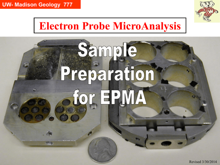
UW- Madison Geology 777 Electron Probe MicroAnalysis Revised 3/30/2014 UW- Madison Geology 777 What’s the point? If it don’t fit in the machine, you ain’t gonna get any numbers. If it ain’t polished right nice and purdy, you ain’t going be able to trust the numbers like you want. If your epoxy ain’t cured nice and solid, it’s gonna bubble and degas inside the probe and make John real unhappy. If it ain’t conductive, it will charge and your numbers will be in the toilet. UW- Madison Geology 777 It does make a difference: Proper sample preparation can be critical to the success of your EPMA work. A successful experiment (creating diffusion couple, achieving multiphase equilibrium, locating critical rock specimen, etc) can be result in unsuccessful EPMA results if the proper sample mounting and polishing is not done. Don’t be hesitant about asking questions. UW- Madison Geology 777 Goals What is your goal? What are the “issues” with your samples? Make sure your sample preparation is appropriate. Do some “dry run” preps before you waste your precious experimental materials. There are several different ways to prepare samples for the probe. Generally people follow in the footsteps of those before them, which is many times correct – but not always. You can learn new tricks from others (I have). Sometimes “normal” sample preparation (usually the polishing aspect) yields a poor result for the type of EPMA the user desires, whereas for another user, they could “make do” with it. An example is a hard brittle material in epoxy. First, cutting rapidly with high speed saw (in a hurry?) fractures the material. Then normal polish (with loose abrasive) easily polishes the softer epoxy and makes rounded edges of the material (the little that is left). This sample would yield lousy diffusion profile data–but you could maybe get a few data points out of the center where the curvature is slight. UW- Madison Geology 777 Sizes Specimen size - mount size - holder size - probe shuttle size: Shuttle: the base we insert into the probe. We have 2 shuttles, both the same size. There are 2 slots along the edges and a hole at the ‘south’ end, all for the insertion rod. Holder: this is the thing we insert into the shuttle; we have many different styles of bases (thin sections, 1”, 1 1/4” and 2” rounds, but they all have the same outside dimensions to fit into the shuttle. It is held in the shuttle by 4 screws. Mount: this is the thing you bring to the lab; your specimen is attached somehow, either embedded in plastic or epoxy, or glued to a glass slide. Round mounts are held in place with set screws; thin sections are held in place with springs. They are top referenced (pushed up from below against a stop) and therefore the complete top must be flat and smooth. Holder Shuttle This is the sample holder for six 1” diameter mounts UW- Madison Geology 777 Sample Mounts 90% of the samples used in EPMA are 1” (outside diameter) rounds, smaller plugs mounted in brass 1” diameter holders, or geological thin sections. The 1” diameter rounds can have the specimens mounted with epoxy inside a 7/8” high phenolic ring forms (e.g., Buehler 20-8151) or 1” diameter compression mounts. There are a few other sample sizes that can be accepted by the probe; ask if you have questions. Do not use the (usually red) soft plastic pipe end covers for molds; they deform (epoxy is exothermic) and yield improper angles. X UW- Madison Geology 777 Mounting grains Many people need to mount crystals or grains. Typically like this: 1.Separate out the grains to be probed 2.Determine what size holder they will need to be mounted in 3.Place he grains on a sticky tape, within the required perimeter 4.Place the round holder over them, sticking firmly to the tape 5.Pour the epoxy over the grains, without creating air bubbles. This can be difficult if using the very small (1/4”) mounts. 6.Wait for hardening 7.Remove and polish (itself a whole other procedure). In 2014, we have come upon an important improvement in step 3. Before, we used regular double-sided sticky tape, which has a tendency to pull up in the middle upon hardening, making it hard to have all small grains polished to the same extent. Now there is Kapton Tape. Much better. UW- Madison Geology 777 Mounts cannot be more than 7/8” maximum height If they are slightly greater, they can be unknowingly forced into the chamber, but they are impossible to remove, and the chamber must be vented to remove them manually. See image to right, view of shuttle upside down, showing mount bottom extending above/ beyond the shuttle bottom surface. UW- Madison Geology 777 Mounting Media Most samples need to be encapsulated for ease of mounting in the probe or SEM and for polishing; encapsulants are normally either * compression mounts, curing at 3-4000 psi, 150°C, using Phenolics or Epoxies or Acrylics *or castable (cold), using Epoxies or Acrylics Do not use epoxies you purchase at a hardware store. Only use ones created for metallographic/microscopic applications (high vacuum, low degassing). There are several suppliers, with Buehler being one commonly used (higher price but excellent product). UW- Madison Geology 777 Epoxy Evaluations The SIMS lab at Edinburgh has a web page where they give the results on a variety of tests of various epoxies used possibly for SIMS work. This is exactly relevant to the needs of an electron microprobe or SEM (vacuum outgassing, beam damage, etc). http://www.geos.ed.ac.uk/facilities/ionprobe/EpoxyResins/ Also valuable sample preparation information from the Stanford SHRIMP lab: http://shrimprg.stanford.edu/Sample%20Preparation.htm UW- Madison Geology 777 Mounting Media - comparison On this and the next slide are 2 tables from the Buehler (online) catalog, reprinted here to give you a feel of the different important parameters to consider in choosing mounting media. UW- Madison Geology 777 UW- Madison Geology 777 Mounting Media - devil in the details • Epoxy mixing and curing: it is very critical to get some things right: *fresh epoxy —old is no good; if not sure, mix up a small batch and make a dummy mount to test it (write date on new epoxy), and *correct proportions (always use a scale to measure the ingredients, and mix well). *Wear gloves, use hood if possible. • Conductive filler: in some cases, it is useful to have a filler (e.g., C, Cu) that is electrically conductive, especially if you do not need/want to carbon coat. UW- Madison Geology 777 Edge Retention Edge retention: how critical is it for your research? If you are looking at diffusion from the very edge inward, it is very important. If so, you need to pay specific attention to media used and to minimizing shrinkage (a filler helps). Cross-sections UW- Madison Geology 777 Cutting, Grinding, Polishing Your goal is to prepare the specimen so that the surface is “mirror smooth” to minimize errors in the matrix correction (path length). Cutting, coarse grinding and then polishing with finer abrasives can introduce various artifacts, which may or may not be relevant to (hinder) your investigation, e.g., plucking of grains; preferential removal of ‘softer’ phases; imparting chemical change and/or deformation to the surface of the sample. Fig 27 from Remond et al (NIST J of Research, 2002, v. 107, p. 639-662): Schematic illustration of physical & chemical modification as a function of depth of a polished material. Clearly the surface becomes more important when operating with low E0 and looking at light elements. UW- Madison Geology 777 Cutting, Grinding, Polishing Polishing is an art (a science) in itself. Originally it fell under the heading of metallography, the science of polishing, etching and microscopic examination of surfaces of materials (using reflected light). One excellent reference that describes “how to” methods is Samuels*. Only a few comments will be made here, mainly as warnings if you intend to do this yourself: * Loose coarse abrasive works OK, but I prefer embedded papers and mylar, “lapping film” (cleaner and less erosion of material). * Different hardness materials in one mount are difficult to polish; best to mount and polish separately if possible. L. E. Samuels, Metallographic Polishing by Mechanical Methods, 1982, 3rd edition, American Society for Metals, 388 pp UW- Madison Geology 777 Cutting, Grinding, Polishing * Length of time spent polishing: Depends on exact situation; sometimes no inherent relationship between time spent and goodness of polish of sample (vs polish of epoxy); you may get very good polish with diamond-embedded mylar in 10 seconds; hours of automatic polishing may grossly erode material and ruin geometry of mount. * Smearing of soft material (phases) is possible*; also tiny fragments of holder material (e.g., brass) is known to get trapped in fractures and in mica cleavage * Broster, B.E. and Hornibrook, E.R.C. (1994) Tin-lead contamination in polished epoxy grain mounts of heavy minerals. Sedimentary Geology, 88, 185-191 UW- Madison Geology 777 Cutting, Grinding, Polishing Two recent accessible* references are papers from the 2002 NIST-MAS workshop on accuracy in EPMA: Implications of Polishing Techniques in Quantitative XRay Microanalysis by Remond, Nockolds, Phillips and Roques-Carmes, NIST J of Research, 107, p. 639-662. Sample Preparation for Electron Probe Microanalysis — Pushing the Limits by Geller and Engle, NIST Journal of Research, 107, p. 627-638. Either from the class webpage www.geology.wisc.edu/~johnf/g777/777NISTarticles.html or the NIST webpage nvl.nist.gov/pub/nistpubs/jres/107/6/cnt107-6.htm UW- Madison Geology 777 Cleaning After polishing, samples must be well cleaned and degreased, to minimize outgassing and contamination of the probe vacuum. Regardless of how or who makes your sample mounts, you are responsible for cleaning and drying. * Put your mount in a small beaker with isopropyl or ethyl alcohol, not acetone, and ultrasonically clean for a few (2-5) minutes (acetone is dirty and can leave a residue upon drying.) However, some compression mounts will dissolve, so ultrasonicate them in solvent for very short period (<1 minute) only if oil or diamond paste (~oil) used. * Rinse 2-5 minutes with distilled water, shake off excess water and blot dry with clean kimwipe (to minimize water marks on surface to be probed). UW- Madison Geology 777 Cleaning * Do not blow water off with building compressed air (oil is in the lines). Do not use canned air (it leaves hydrocarbons on the surface). * Then dry on a hot plate or oven at low heat to remove all adsorbed water. UW- Madison Geology 777 Carbon Coating Non-conductive samples (e.g,. rock thin sections) will need to be carbon coated. They should be coated with the Probe Lab’s evaporator in Room 307; this is normally done by lab personnel, though students who have lots of thin sections to coat can be trained. Experience has shown that coating elsewhere with carbon sputtering does not yield favorable quantitative results on the probe here. Old samples that were coated many years ago should probably have their coats cleaned (i.e., with <1 m alumina or silica) and then recoated. Watch your eyes! UW- Madison Geology 777 Carbon Coating —Thickness We monitor the thickness of carbon by observing the interference colors on a polished brass mount (Kerrick et al, 1973)* Variation in the carbon thickness between standard and unknowns can create additional uncertainty and error: 1) the electrons entering the specimen lose energy passing through the coating, reducing the x-ray intensity produced within the specimen, and 2) emergent x-rays are absorbed by the carbon as they leave the sample on the way to the detector. These effects are largest for the “light” elements, but also higher Z elements also.** 150Å Orange 200Å Indigo red 250Å Blue 300Å Bluish Green 350Å Green Blue 400Å Pale Green 450Å Silver gold Color representatives not very accurate! Need to see Indigo Red. * Kerrick, D. M., Eminhizer, L.B. and Villaume, J.F. (1973) The role of carbon film thickness in electron microprobe analysis, Am. Min., 58, 920-925. ** Armstrong, J.T. (1993) Effects of carbon coat thickness and contamination on quantitative analysis: a new look at an old problem, in Proceedings of the 27th Annual MAS Meeting, S13-14 UW- Madison Geology 777 Carbon Coating —Light Elements If you are analyzing “light elements” (F, O, C, N, B) in insulators that require conductive coating, it is critical that your samples and standards be coated simultaneously, preferably in a rotating apparatus, for even coating. Donovan will probably be implementing a carbon-coat thickness option in Probe for EPMA, so for high accuracy, C Ka can be measured on both standards and unknowns and the various values computed within the matrix correction. Armstrong, J.T. (1993) Effects of carbon coat thickness and contamination on quantitative analysis: a new look at an old problem, in Proceedings of the 27th Annual MAS Meeting, S13-14 UW- Madison Geology 777 Stained Mounts — NOT IN THE PROBE! There are occasions where thin sections are stained to distinguish various phases (carbonates, feldspars). Samples that have been stained ARE NOT ALLOWED TO BE PUT INTO THE ELECTRON MICROPROBE. One probe laboratory where high current hit the stain/dye had a catastrophe where the optical components (mirrors and lenses) were coated with the stain and it was VERY EXPENSIVE to repair. UW- Madison Geology 777 Storage Protect your specimen mounts! * Avoid touching surface with fingers, use gloves if possible. * Do not wrap in kleenex (paper fibers); if necessary, use kimwipe instead * Keep in containers: plastic boxes of various sizes are available in the lab; also cardboard boxes for 25 rectangular thin sections * Label the boxes with your name, so if you leave them in the lab they can find their way back to you. (Durphy Packaging in PA sells many sizes of small plastic boxes; Palouse Petro Products sells inexpensive cardboard boxes for thin sections.) UW- Madison Geology 777 Documentation - Navigation If your samples have any ambiguities or complexities, it pays well to make maps or drawings beforehand, showing orientations (e.g., North arrow) and regions of interest. It is difficult to find a 100 micron grain in a 25000 micron forest without landmarks. We now can scan mounts, import the images to the Probe for EPMA software, “register” the image with actual stage coordinates, and then click on the image to move to that area. Slick!
