ATFreview20130403naito
advertisement

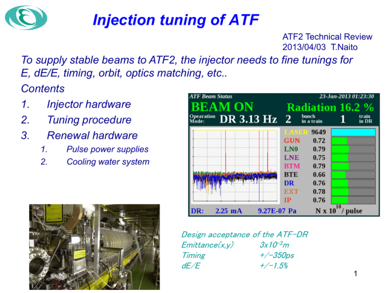
Injection tuning of ATF ATF2 Technical Review 2013/04/03 T.Naito To supply stable beams to ATF2, the injector needs to fine tunings for E, dE/E, timing, orbit, optics matching, etc.. Contents 1. Injector hardware 2. Tuning procedure 3. Renewal hardware 1. 2. Pulse power supplies Cooling water system Design acceptance of the ATF-DR Emittance(x,y) 3x10⁻³m Timing +/-350ps dE/E +/-1.5% 1 1.28GeV ATF Injector 1. S-band linac 1)Laser triggered RF Gun(CsTe cathode) 2)Pre-injector 3m long Acc. Structure x1 3)3m long Acc. Structure x 18 2. Beam Trans port 3. DC septum, Injection kicker(on axis injection) E=1.28GeV Ne=1x10¹⁰ e-/bunch Bunch#/shot 1 ~ 20 bunches Bunch spacing 2.8~5.6ns Rep=3.12Hz(12.5Hz max) Normalize Emittance=3x10⁻⁵ m 2 Gun and Pre-injector Mode lock Laser Cathode Load lock system is used to replace new one. Bunch Current 3 Linac #0 #1 #2 #3 #4 #5 #6 The high power pulse RF is produced by 11 klystrons. #0 RF gun + 1st Accelerator structure #1~#8 Two Accelerator structures using SLED #9, #10 Single Accelerator structure for the Energy compensation of muti-bunch beam acceleration (#9, #10 are not used for the single bunch acceleration.) #7 #8 #9#10 Septum and kicker region Septum chamber aperture 7 x 22 mm for injection beam Kicker chamber aperture 16mm diameter 5 Injection tuning(1) Gun and linac tuning The beam emission is controlled by the laser power and the phase. Especially, the beam quality is very sensitive with the phase between the laser and the RF cavity. The beam energy is adjusted by the phase control of all klystrons. E and dE/E is confirmed by a screen monitor at the end of the linac. Left picture : the beam emission characteristics for the laser phase. Bellow picture : phase control window of all klystrons. Injection tuning(2) Orbit and Matching tuning The orbit and matching control is done by the popup window for each device. We are using many monitors, BPMs, Current monitors, Screen monitors, loss monitors, etc., by looking these monitors, the beam is steered to the end of BT. The difficulty is that the beam conditions are strongly depend on the linac condition. Left picture : BPM measurement, the red line shows present orbit and the black line shows previous orbit, which means the orbit change is happen so often. Injection tuning(3) Fiber loss monitor Fiber loss monitor Fiber loss monitors were installed for all area of the ATF to detect the beam loss at each location. It is useful tool for the beam tuning. Feature 1)It is easy to find out the beam loss location. 2)High sensitivity 3)Need to check the radiation damage Injection tuning(3) Fiber loss monitor Example of beam loss The beam loss location can be found for each location. The tuning try to minimize the beam loss. 1) Chicane or L0 2) Between MS3L to MS5L 3) L1 input 4) L3 input Injection tuning(4) 11Mar2011 According to the environment temperature, the circumference of the DR changes. The RF frequency of the DR RF cavity(714MHz) is changed to adjust the center orbit of the DR. The linac frequency is synchronized with the DR RF frequency. Consequently, to adjust the center orbit of the DR, the linac frequency(2856MHz) is often changed. According to the frequency change, the temperature of the cooling water of the SLED has to be changed. The graphs show the history of the changing frequency and the estimated circumference change. The circumference changed after Mar11. Renewal of the klystron PS(1) Stabilization of the klystron power supply is key issue for the stable beam. Each klystron power supply has different history and different hardware. Especially, the common DC High Voltage power supply(common DC HV PS) is located outside of the building, which made many troubles. The replacement of the power supplies from the common DC HV PS to the switching HV PS is now in progress. ATF Building DC HV PS Renewal of the klystron PS(2) Apr/2013 All switching PS Oct/2013 All compact modulator Old type modulator Compact modulator Renewal of the cooling water system The linac cooling water system was fabricated in 1990, which supplies the cooling water for the accelerator structures. It is very old and the cooling power reduced year by year. At the every spring run, especially high temperature day time, the system was often down for the over heating. The low repetition rate operation of the linac is effective to avoid the system down. The replacement to a new cooling water system is scheduled in this summer 13 shutdown. Summary The effort of the injection tuning was improved by using many monitors, especially, the fiber loss monitor is effective(thanks to D. McCormick SLAC), which is used not only linac and BT, but ATF2 beam line. The tuning time was reduced from 1 shift to half shift to store the ordinary current. The hardware renewal is scheduled to improve the stability. 1.Common HV-PS is replaced to switching PS. (2013/04) 2.Pulse modulator is replaced to compact type. (2013/summer) 3.Cooling water system of the linac is replaced to new one. (2013/summer) Backup 15 ライナック冷却水システム 冷却水システムは、1600L/minのメイ ンに400L/minのサブを足すという設 計で安定性から見るといい設計では ない。 Return Sub (4)30℃系 Main (3)30℃系 (2)22℃系 (1)7℃系 SLED The Q-value,10^5, is very high, so the tuning frequency is very sensitive with the temperature. 17 #8 SLED tuning(20091008) SLED 波形 Tuning 前 De-tunerを入れる。 片側のみtuning Tuning 後 調整後、 完全にではないが8台全ての SLEDに対して周波数の調整 が出来た。


![Overview - Indico [Home]](http://s3.studylib.net/store/data/007100640_1-3c71c8a148d7b4963162c694b3cc23f9-300x300.png)
