a) 3 operating lines
advertisement

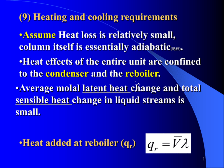
(9) Heating and cooling requirements •Assume Heat loss is relatively small, column itself is essentially adiabatic . •Heat effects of the entire unit are confined to the condenser and the reboiler. •Average molal latentqheat and total r Vchange sensible heat change in liquid streams is small. (绝热) •Heat added at reboiler (qr) qr V 1 a x FF x x F Condenser a q F L n n L ywa a c Va n T1 m VLa xn q(cT2 T Va x F n n n Ln x T2 L a out y Heat a n a Control n y xan xn Vn 1Accumulator D y V L a L a n surface 1 Ln xa qc LVLanVnn y xnn Lxann 1n 1 n 1 y La xD a Overhead Reflux xnn x xnyLn nm D q 1 c VnL1n xVyannn11 product V b x L a m a a VnL1n x V xD n n 1 Lm D y nxn1 qm F yb Vb yc nLL1mn Vb q Feed q x y nxn1 cy Vn 1 c a x n 1 L mVn 1 Dmmxxmn m L x F xm D y yb b FV y b D n 1 V D m q b1 [Fig.21.8(p.649)] xmVVmV c m Lmynn11 xL 1 Lb x F VaLmy n 1 x DLmymVn 1 y xbV Lb xD xmm VxDmmmyLm1nyb11m b1 D b xb Va y xaVmm yxmmymmb1LVb1qry xb Reboiler 1 b x bD Vmmm mLm 1 Control q x1m r B V L Heat in q r q V r m 1 surface y 2 a Laymxm1 L x m 1 y LV b by L m m1 m m1 a m 1 m 1 b b m 1m B my1 m 1 mb r b b m S yx x B Bottoms product y La x mV 1 m xx1 q L x V B 2 qr V •Steam consumption m S (21.32) S S (蒸汽消耗量) kW qqqrrr =heat added at reboiler m SSS=steam consumption m m Vb VVV =Vb, vapor rate from reboiler yb Vb Vb SSS =latent Lb yb heat of steam yb Vb xb Lb latent heat of mixture Lb Vb yb =molal Vb q r xb xb yb LV b b yb Reboilerq r B qr Heat in q r Lb xbyb Lb m S x B B Bottoms product B xb q rLb xb V kg / s km ol/ s kJ / kg kJ / kgm ol 3 a •If condensate is not subcooled, •heat removed in condenser: qc V (V=Va) VxaF Condenserx a Va w y a T1 m ya La T2 La qc (T Heat out D xxa a xD •Water consumption/Cooling water flow qq rate qc V w m c pc (T2 T1 ) c pc (T2 T1 ) cc D D xxDD (21.33) qqrc =heat removed in condenser kW W ; Btu / h m m kg / s V wS =water consumption kg / h; lb / h ) (T2 V VT1 ) =temperature rise of cooling C C water SS cal / g 4 •*[For enthalpy balances in detail, see pp.672-675](自学) •EXAMPLE 21.2 [(c)(d)] 5 (10) Minimum number of plates最小理论板 数/Total reflux全回流 •Effect of reflux ratio on number of plates: RD N (num ber of ideal plates) RD max N N min Why ? RD min ( ?) N Why ? •When total reflux, (1) D 0, B 0, F 0 0 (2) RD(1) LD / D0,LB/ 00,RFD max then LN / Dboth (num L coincide重合 / 0ber of ideal (3) lines with theplates) (3)Operating yn1(2) R xR nD D diagonal, (3) RyDnmax 1 x n N N min Why ? 6 Equilibrium line Operating line xB xD RD N (num ber of ideal plates) xB xD RD flow Total reflux max N N min Why ? 7 RD N (num ber of ideal plates) •MethodRfor Computing D max N N min Why ? R ( ?) N Why ? D min •(1) Constructing method: constructing steps on an x-y diagram between compositions xD and xB, using 45°line as the operating line for both sections of the column. •(2)Analytic method for ideal mixtures (pp.665-666) ln[xD (1 xB ) / xB (1 xD )] N min 1 ln AB (21.42) •Nmin is the ideal plates needed, not including a reboiler. 8 ln[xD (1 xB ) / xB (1 xD )] N min 1 ln AB (21.42) •Equation (21.42) ln[ x (1is the x ) Fenske / x (1 equation x )] (芬斯克方程) , N min 1 (21.4 ln[ xwhen xB )AB/ is xBconstant. (1 xD )] If the •Which applies ln D (1 N min 1 (21 change in the value ofln ABfrom the bottom of D B B D the column to the top is moderate, a ln[ xD (1 ofxthe xB (1 xDvalues )] B ) / extreme geometricmean N min 1 is (21.42) recommended forln AB . 9 B (11) x F Minimum reflux(最小回流比)/Infinite number of plates(理论板无穷多) xD x a c g RD N y d •When the intersection of the e two operating lines falls on the f xB x B equilibrium line xF (point d), x xB xD F b N , R R D Dm x x F x xB D Fig.21.19 Minimum x ratio最小回流比 10 x D y reflux xF D RD N •When the intersection of the two operating lines falls on the equilibrium line (point d), N , RD RDm RDm =minimum reflux ratio •All actual columns operates at a reflux ratio between the minimum and infinity . (无穷大) RDm La La RD D D min (21.43) 11 •For the normal type of equilibrium curve, xB RDm xD y xD y x F RDm (21.44) RDm 1 xD x y x xD x g c y a d e f xB b xB xF xB xB xD x F x xF xD 12 •Eq.(21.44) cannot be applied to all systems. •For example, ethanol-water system, abnormal equilibrium curve. 13 a xD c RDm 1 xD xD RDm 1 xD RDm 1 xD xF xD xD RDm 1 xB xF xD xF x xFcan be B reflux ratio •In such a situation the minimum x B the slope of the operating line ac that computed from xB is tangent to the equilibrium curve. 14 •Question: Is it the only way that the minimum reflux ratio must be found by drawing the operating line that is tangent to the equilibrium curve for abnormal equilibrium curve? •Factors influencing RDm include: (1)Equilibrium relation (curve); (2)xD, xF, xB; (3)q (Thermal condition parameter of feed). Therefore, it is not the only way for determining RDm by drawing the operating line that is tangent to the equilibrium curve for abnormal equilibrium curve. •For example, … 15 (12)Invariant zone夹紧区/恒浓区 Pinch Point a Pinch point d f b •Invariant zone: At minimum reflux ratio, near pinch point夹紧点, where there is no change in either liquid or vapor concentrations from plate to plate,so xn1 xn , yn1 yn 16 (13)Optimum reflux ratio适宜回流比 RDm RD • Effect of Reflux ratio on distillation: Given ,WhenRDRD, , Given FF,,xxFF, ,xxDD, x, Bx,BWhen , ((aa)) N esesononequipm entent Fixed Fixed chcharg arg equipm ,, V n ndiam eter Fixed ch a equipm ((bb)) Lent V ,,VV colum colum diam eter Fixed Given F , xF , xD , xB ,When RD , m eter Fixed es ononequipm equipm (a) N Fixed ch charg arg es entent Given F , xF , xD , xB ,When RD , Fixed charges on reboiler and ((ca)) LN , L Fixed ,V ,V ch colum n diam eter Fixed ch ar arg es on equipm ent condenser Steam nand cooling-water costs (d ) L ,V colum diam eter Fixed ch arg es on 17 Minimum reflux ratio Annual cost Total Steam c ) 2 ( + ) 1 ost=( ,(1) s t s o c r e t a w ing l o o c and Optimum reflux ratio Fixed charges on equipment,(2) RDm RDopt Reflux ratio Figure 21.21 18 •The total cost reaches a minimum at a definite reflux ratio, that is , optimum reflux ratio RDopt. •The optimum reflux ratio depends on the cost of energy; it will be closer to RDm when energy costs are relatively high, and farther from RDm when distillation equipment is made of expensive alloys. •RDopt=(1.1~2.0)RDm •[EXAMPLE 21.3][p.670] 19 (14)Nearly pure products •When either the bottom or overhead product is nearly pure, a single diagram covering the entire range of concentrations is impractical as the steps near x=0 and x=1 become small. •Method 1: Auxiliary diagrams on a large scale •[calculations are usually done by computer]. 20 •Method 2: Using Eq.(20.27) or (20.28). •[At each end of the equilibrium curve, both the equilibrium and the operating lines are straight, so Eq.(20.27) can be used, and no graphical construction is required] •[Basis: Raoult’s law applies to the major(主要 的) component and Henry’s law to the minor (次要的)component at each end of the equilibrium curve. ]?[p.671] •[EXAMPLE 21.4.] 21 (15) Some special cases of distillation • a side-stream draw off (自学): a) 3 operating lines; 2 q-lines (feed lines); b) Equations of operating lines: Equations of operating lines of top and bottom sections are the same as that of the rectifying and stripping sections discussed before. The equation of operating line in the middle section of the column has to be derived. 22 2 2 1 , xD , q 3 D 3 3 3 2 F , x , q F, ,qxF B , q, x B F F , x 3 F F , xF , q D, x D D, xD Assuming F , xF D ,Lq, xD V D, xD , q D, x D molal D, x D D V, xLD , q D, x , qconstant 1 B, xB y S11 D, xDB ,,qxV L BV V yS 1 B , x B 2 S L L V V y S 1 L 3 L VLxS y S 1 V F , xF ,Lq xLS V D, x D xS V L D, xD , q V B, x B Fig. for Ex.21.11 1D, x , qD overflow in this D 1 B, xB column. By L2 2 B, x B material xS3 3 2 V V balance: 1F , xF, q3x y, qS 1 F y S 1F V yS 1 LxS DxD Dx D 2D, x F ,LxF , q L DxD Dx D D D , xD L yS 1 xS 3D, x ,Dq,xxD V V DDx xD S, q FB,, xxF , qSD, xD , q B B , xB D 23 D B, x B V ,xV Assuming constant molal overflow in this column, equation for the operating line of V yS 1 LxS DxD Dx D middle section is L DxD Dx D yS 1 xS V V The upper operating line is given by Eq.(21.13) L DxD yn 1 xn (21.13) V V L Dx yn 1 Lxn BxD (21.13) The lower operating line is given by Eq.(21.16) ym 1 V xm V B (21.16) V V L Bx ym 1 xm B (21.16) V V 24 L L D, L L The operating lines for the 3 sections are shown in the x V VB V following diagram. Dashed Lx F L lines are for RDm=(L/D)min. q 1 V x D V q 1 xD q 1 (虚线) y F q 1 DxD Dx D DxD Dx D V L DxD xn V V L BxB xB (21.13) xB xB xF xB xF xF xD xD xD 25 How to determine the number of ideal plates? 26 (b) Direct steam heating直接蒸汽加热 •Live steam is injected directly below the bottom plate. •Equation of operating line of the rectifying section is the same as that discussed before. •The equation of operating line in the stripping section of the column has changed. 27 B , x V0 , y0 F , xD B F , xD D, x D m B, xBF , xVF 0 , y0 F , x F D, xLD V0 , yB0 , xBm D, x D B , x B F , xF m V0 , yL0 V F , xF V , y B, xxB 0 0L m V m B, x B m V0 , yy0 L xm m 1 V V0 , y0 L m xD xm V ym 1 D,m L V F , xF ym 1xm L BSteam , xB V xmD, x y D m 1 V y m 1 V0 , y0 xm F , xF xm m ym 1 B, x B y m 1 Assuming constant molal overflow in this column. By material balance: L V0 V B Lxm V0 y0 V ym1 BxB [ y0 0, L B,V V0 ] B BxB ym1 xm V0 V0 28 L V0 V B Lxm section V0 y0 Voperating ym1 BxB line is given by The stripping the following [ y equation 0, L B,V V ] 0 0 B BxB ym1 xm V0 V0 The rectifying section operating line is given by Eq.(21.13) L DxD yn 1 xn V V L BxB ym 1 xm V V (21.13) (21.16) 29 Fig. Live steam is injected directly below the bottom plate. How to determine the number of ideal plates? xB xB xB xF xF xD 30 •which cases will live steam be used for in distillation? •Water soln(水溶液). Bottom product nearly pure water. 31


