Lecture 1: Rotation of Rigid Body
advertisement
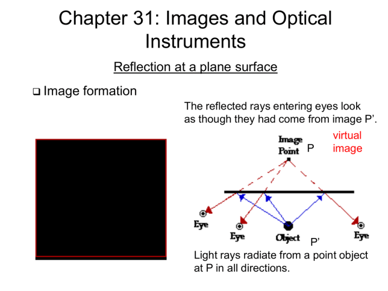
Chapter 31: Images and Optical Instruments Reflection at a plane surface Image formation The reflected rays entering eyes look as though they had come from image P’. virtual P image P’ Light rays radiate from a point object at P in all directions. Reflection and refraction at a plane surface Image formation Reflection and refraction at a plane surface Image formation i (or s’) is the image distance s is the object distance: |s| =|i| s’ Sign Rules: (1) Sign rule for the object distance: When object is on the same side of the reflecting or refracting surface as the incoming light, the object distance s is positive. Otherwise it is negative. (2) Sign rule for the image distance: When image is on the same side of the reflecting or refracting surface as the outgoing light, the image distance i ( or s’) is positive. Otherwise it is negative. (3) Sign rule for the radius of curvature of a spherical surface: When the center of curvature C is on the same side as the outgoing light, the radius of the curvature is positive. Otherwise it is negative. Reflection at a plane surface Image formation image is erect image is virtual h Multiple image due to multiple Reflection by two mirrors h’ m = h’/h=1 lateral magnification Reflection at a plane surface Image formation When a flat mirror is rotated, how much is the image rotated? Reflection at a spherical mirror Concave and convex mirror Reflection at a spherical mirror Focal points at concave and convex mirror Focal point or focus: Point F at which rays from a source point are brought together (focused) to form an image. Focal length: Distance f from mirror where focus occurs. f=R/2 where R is the radius of a spherical mirror. Reflection at a spherical mirror Focal points at a concave mirror 2 tan h /( s d ) tan h /( s'd ) h object d image If s , s' R / 2 s’ tan h /( R d ) h/s h / s' if d s, s' h/R 1 1 2 1 s s' R f Reflection at a spherical mirror Image of an extended object at a concave mirror real image Principle rays: Light rays that can be traced (more easily) from the source to the image: 1. Parallel to optical axis 2. Passing through the focal point 3. Passing through the center of curvature 4. Passing through the center of the mirror surface or lens Reflection at a spherical mirror Magnification of image at a concave mirror h h’ h' s' f m h s f s When s,s’ >0 , m<0 inverted s/s’<0, m>0 upright or erect Reflection at a spherical mirror Example with a concave mirror real image real image real image virtual image Reflection at a spherical mirror Example with a concave mirror Reflection at a spherical mirror Image at a convex mirror 1 1 2 1 s s' R f s s’ f f s' f m s f s R s positive s’ negative (virtual image) R negative f negative Reflection at a spherical mirror Magnification of image at a convex mirror height at s height at s' s s' For a convex mirror f < 0 height at s s' 1 1 1 m , height at s' s s s' f s’ s' f m s f s m > 1 magnified m < 1 minimized m > 0 image upright m < 0 image inverted Refraction at a spherical surface Refraction at a convex spherical surface 1 For small angles 12 sin n11 n22 BF (1 2 ) AB f AB /(1 2 ) AB R1 R1 /(1 2 ) Rn2 /(n2 n1 ) 1 1 f ( n2 )R n2 n1 Refraction at a spherical surface Refraction at a concave spherical surface For a concave surface, we can use the same formula n2 f ( )R n2 n1 But in this case R < 0 and f < 0. Therefore the image is virtual. Refraction at a spherical surface Relation between source and image distance at a convex spherical surface s’ 1 2 n1 ( ) n2 ( ) AB R AB s s' Snell’s law AB AB AB AB n n n n ) n2 ( ) 1 2 2 1 R s R s' s s' R For a convex (concave) surface, R >(<) 0. n1 ( Refraction at a spherical surface Example of a convex surface |s’| Refraction at a spherical surface Example of a concave surface |s’| Refraction at a spherical surface Example of a concave surface Refraction at a spherical surface Example of a concave surface Convex Lens Sign rules for convex and concave lens: Sign Rules: (1) Sign rule for the object distance: When object is on the same side of the reflecting or refracting surface as the incoming light, the object distance s is positive. Otherwise it is negative. (2) Sign rule for the image distance: When image is on the same side of the reflecting or refracting surface as the outgoing light, the image distance i (or s’) is positive (real image). Otherwise it is negative (virtual image). (3) Sign rule for the radius of curvature of a spherical surface: When the center of curvature C is on the same side as the outgoing light, the radius of the curvature is positive. Otherwise it is negative. Convex Lens Lens-makers (thin lens) formula surface 2 surface 1 s’ Image due to surface 1: s’1 becomes source s2 for 1 n n 1 1 n 1 1 ' ' s1 s1 R1 s1 nR1 ns1 n 1 1 n 1 1 1 n ' ' ' surface 2: s2 s2 R2 s1 s2 R2 n( s1 = s and s’2 = s’: R1>0 R2<0 n 1 1 1 1 n ) ' nR1 ns1 s2 R2 1 1 1 1 1 (n 1)( ) s s' R1 R2 f Parallel rays (s=inf.) w.r.t. the axis converge at the focal point Convex Lens Magnification s’ m II ' / SS' SS' P II ' P m s' f s f s s' m s same as for mirrors Convex Lens Object between the focal point and lens A virtual image Convex Lens Object position, image position, and magnification real inverted image m<1 real inverted image m >1 virtual erect image m >1 Types of lens Lens Lens Two lens systems Lens Two lens systems (cont’d) Lens Two lens systems (cont’d) Lens Two lens systems (cont’d) Eyes Anatomy of eye Eyes Near- and far-sightedness and corrective lenses farsightedness nearsightedness Angular size h d h s d i m s In general the minimum distance d=dmin~25 cm at which an eye can see image of an object comfortably and clearly. Magnifying glass s’ hi i s h virtual image 1 1 1 s' f s the eye is most relaxed s' m when s f s' but s the minimum distance at which an eye can see image of an object comfortably and clearly. hi m h h h tan i i ( )s f | s' | | s' | s f h/ f d M m i min , d min 25 cm for human eye. s h / d min f Microscope 2i L i f1 , f 2 f1 , f 2 small magnifier h1 | m | h0 Lh0 / f1 ( | m | i / s1 L / s1 L / f1 ) Object is placed near F1 (s1~f1). Image by lens1 is close to the focal point of lens2 at F2. image ang. size 2i h1 / f 2 ( Lh0 ) /( f1 f 2 ) ( i hi / i h / f for a magnifier) M m 2i / object [(Lh0 ) /( f1 f 2 )] /[h0 / d min ] ( Ld min ) /( f1 f 2 ) Refracting telescope Image by lens1 is at its focal point which is the focal point of lens 2 image distance after lens1 h1 m h0 s' h0 / s s' s f1 s ( s ) image height by lens1 at its focal point magnifier i h1 / f 2 s f1 / f 2 m i / object i / s f1 / f 2 angular size of image by lens2; eye is close to eyepiece Reflecting telescope m i / object f1 / f 2 Aberration sphere paraboloid Chromatic aberration Gravitational lens Problem 1 Exercises What is the size of the smallest vertical plane mirror in which a woman of height h can see her full-length? Solution x The minimum length of mirror for a woman to see her full height h Is h/2 as shown in the figure right. x/2 (h-x)/2 h-x Exercises Problem 2 (focal length of a zoom lens) ray bundle r0 f2=-|f2| f1 Q r0 x f1 I’ r’0 d s2 d (variable)< f1 |f2|>f1-d s’2 f ' (a) Show that the radius of the ray bundle decreases to r0 r0 ( f1 d ) / f1 x r0 r0' r0' r0 x r0 r0 (d / f1 ) r0 ( f1 d ) / f1 Exercises Problem 2 (focal length of a zoom lens) ray bundle r0 f2=-|f2| f1 Q f1 I’ r’0 r0 x d s2 s’2 d (variable)< f1 f (b) Show that the final image I’ is formed a distance to the right of the diverging lens. s2 d f1 s2' f 2 ( f1 d ) /( f 2 f1 d ) f f1 d f ( f d) 1 1 1 1 d f1 f 2 ' ' 2 s2' 2 1 d f1 s2 f 2 s2 f 2 (d f1 ) f 2 ( f1 d ) f 2 f1 d Exercises Problem 2 (focal length of a zoom lens) ray bundle r0 f2=-|f2| f1 Q r0 x f1 I’ r’0 d s2 s’2 d (variable)< f1 f (c) If the rays that emerge from the diverging lens and reach the final image point are extended backward to the left of the diverging lens, they will eventually expand to the original radius r0 at some point Q. The distance from the final image I’ to the point Q is the effective focal length of the lens combination. Find the effective focal length. f 2 ( f1 d ) f1 f 2 r0' r0 r0 ' f1 f s f 2 s2' f r0' f1 d f 2 f1 d f 2 f1 d

