SDSU_9_Damman
advertisement
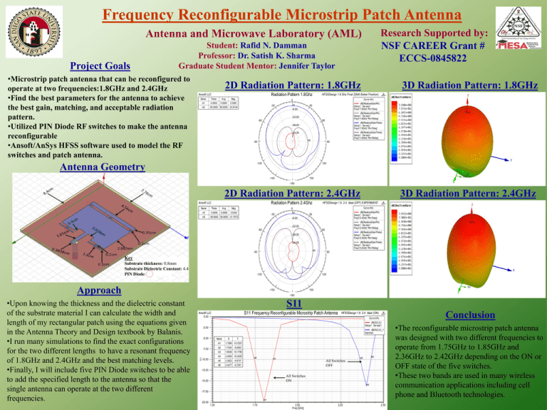
Frequency Reconfigurable Microstrip Patch Antenna Research Supported by: NSF CAREER Grant # ECCS-0845822 Antenna and Microwave Laboratory (AML) Project Goals Student: Rafid N. Damman Professor: Dr. Satish K. Sharma Graduate Student Mentor: Jennifer Taylor •Microstrip patch antenna that can be reconfigured to operate at two frequencies:1.8GHz and 2.4GHz •Find the best parameters for the antenna to achieve the best gain, matching, and acceptable radiation pattern. •Utilized PIN Diode RF switches to make the antenna reconfigurable •Ansoft/AnSys HFSS software used to model the RF switches and patch antenna. 2D Radiation Pattern: 1.8GHz Radiation Pattern 1.8Ghz Ansoft LLC Name Theta Ang Mag m1 0.0000 0.0000 2.0282 m2 HFSSDesign 1.8 Ghz Final (SMA Better Position) 90.0000 90.0000 -33.6144 m1 dB(RealizedGainPhi) Setup1 : Sw eep1 Freq='1.8GHz' Phi='0deg' 30 -6.00 dB(RealizedGainPhi) Setup1 : Sw eep1 Freq='1.8GHz' Phi='90deg' -22.00 -60 60 dB(RealizedGainTheta) Setup1 : Sw eep1 Freq='1.8GHz' Phi='0deg' -38.00 dB(RealizedGainTheta) Setup1 : Sw eep1 Freq='1.8GHz' Phi='90deg' -54.00 m2 -90 90 -120 Antenna Geometry ANSOFT Curve Info 0 -30 3D Radiation Pattern: 1.8GHz 120 -150 150 -180 2D Radiation Pattern: 2.4GHz Radiation Pattern 2.4Ghz Ansoft LLC Name Theta Ang Mag m1 0.0000 0.0000 3.5342 m2 90.0000 90.0000 -21.7073 HFSSDesign 1.8 2.4 Ideal (OFF) EXPERIMENT -30 dB(RealizedGainPhi) Setup1 : Sw eep1 Freq='2.4GHz' Phi='0deg' 30 -6.00 dB(RealizedGainPhi) Setup1 : Sw eep1 Freq='2.4GHz' Phi='90deg' -22.00 -60 60 dB(RealizedGainTheta) Setup1 : Sw eep1 Freq='2.4GHz' Phi='0deg' -38.00 dB(RealizedGainTheta) Setup1 : Sw eep1 Freq='2.4GHz' Phi='90deg' -54.00 m2 -90 ANSOFT Curve Info 0 m1 3D Radiation Pattern: 2.4GHz 90 Key Substrate thickness: 0.8mm Substrate Dielectric Constant: 4.4 PIN Diode: -120 120 Approach 150 -180 S11 S11 Frequency Reconfigurable Microstrip Patch Antenna Ansoft LLC HFSSDesign 1.8 2.4 Ideal (ON) 0.00 ANSOFT Curve Info dB(S(2,2)) Setup1 : Sw eep1 -2.50 dB(S(2,2))_1 Imported -5.00 Name -7.50 Y1 •Upon knowing the thickness and the dielectric constant of the substrate material I can calculate the width and length of my rectangular patch using the equations given in the Antenna Theory and Design textbook by Balanis. •I run many simulations to find the exact configurations for the two different lengths to have a resonant frequency of 1.8GHz and 2.4GHz and the best matching levels. •Finally, I will include five PIN Diode switches to be able to add the specified length to the antenna so that the single antenna can operate at the two different frequencies. -150 -10.00 X Y m1 1.7999 -19.7207 m2 1.7434 -9.9263 m3 1.8536 -10.1796 m4 2.4000 -16.2450 m5 2.3622 -9.9737 m6 2.4277 -9.7291 m2 m3 All Switches OFF m6 m5 -12.50 All Switches ON -15.00 m4 -17.50 m1 -20.00 1.50 1.75 2.00 Freq [GHz] 2.25 2.50 Conclusion •The reconfigurable microstrip patch antenna was designed with two different frequencies to operate from 1.75GHz to 1.85GHz and 2.36GHz to 2.42GHz depending on the ON or OFF state of the five switches. •These two bands are used in many wireless communication applications including cell phone and Bluetooth technologies.
