Mosaic Detector: Experiments for Therapy and Space Research
advertisement
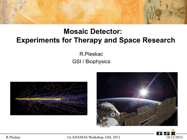
Mosaic Detector: Experiments for Therapy and Space Research R.Pleskac GSI / Biophysics R.Pleskac 1st ADAMAS Workshop, GSI, 2012 18/12/2012 Overview Hadrontherapy & Space Research Significance of nuclear fragmentation Cave A measurements (Bragg curves, nuclear fragmentation, microdosimetry, beam widening) FIRST experiment (double-differential cross-section for Z particles) Mosaic Detector Requirements Design Time Line R.Pleskac 1st ADAMAS Workshop, GSI, 2012 18/12/2012 Significance of nuclear fragmentation in RT with light ions High-energy carbon beam stopping in water I. Pshenichnov Exp. Investigations (physical characterization) Nuclear fragmentation – – – LBLLoss Berkeley Ne 670 1970’s W. Schimmerling of primary ionsMeV/u depth-dose, RBE NIRS/HIMAC Chiba C, light ions 1990’s T. Kanai Total reaction cross section1990’s 1-2 b GSI Biophysics C, light ions Carbon ion therapy 100-400 MeV/u Buildup of secondary fragments dose-tail, lateral dose R.Pleskac 1st ADAMAS Workshop, GSI, 2012 18/12/2012 Before treatment Definition and delineation of target volume (CT,MRI,PET) transform patient CT-data to water-equivalent path length of ions Treatment planning: - find best entrance ports - optimization (absorbed dose [Gy]) physical model - biological optim. (RBE (LET(Z,E),dose …) [GyE]) Verify dose distribution in water phantom (tolerable deviation < 5%) Patient positioning Patient treatment R.Pleskac Bragg curves + fragmentation data 1st ADAMAS Workshop, GSI, 2012 18/12/2012 Precision Bragg curve measurements The present data base includes precise B.P. position data for p, 3He, 7Li, 12C, 16O Mechanical accuracy: 1 μm for relative thickness 0.1 mm absolute Comparison of absolute B.P. positions measured at GSI and HIT synchrotrons at the same nominal beam energies: → agreement within < 2 ‰ rel. deviation R.Pleskac 1st ADAMAS Workshop, GSI, 2012 18/12/2012 Bragg curves of 12C water peak-width and height are affected by – straggling – fragmentation increasing tail dose © D.Schardt R.Pleskac 1st ADAMAS Workshop, GSI, 2012 18/12/2012 Microdosimetry in-phantom measurements Tissue-equivalent proportional chamber (TEPC) Sensitive volume 120 mb TE-gas R.Pleskac 1st ADAMAS Workshop, GSI, 2012 18/12/2012 Beam Widening – - Film Stack in Water Acquarium Stack of films placed in the waterphantom aligned with the beam axis Irradiated GaF Chromic films Photo© G.Martino R.Pleskac 1st ADAMAS Workshop, GSI, 2012 18/12/2012 Fragmentation studies - Fragment buildup in thick targets - Neutrons - Microdosimetry R.Pleskac 1st ADAMAS Workshop, GSI, 2012 18/12/2012 Fragmentation Setup The ΔE–E telescope detector Angular distribution setup → Beam energy of 120 MeV/u → Cylindrical water target (diameter of 150 mm) → Telescope positionned at 0°, 20°, 30°, 60°, 90° and 120° R.Pleskac Loss of primary ions setup → beam energy of 300 MeV/u → Target: 0, 1, …, 7 large water flasks → Telescope positionned at 0° 1st ADAMAS Workshop, GSI, 2012 18/12/2012 Signal processing & Data Acquisition (DAQ) system Number of primary ions N0 → big ionization chamber Number of fragments N → ΔE-E telescope Trigger → START and/or BaF2 detector DAQ → GSI Multi Branch System (MBS) → Aug 2007 – CAMAC CVC based DAQ → Feb 2009 – CAMAC GTBC based DAQ → Aug 2012 – VME based DAQ RAW DATA → List Mode Data (LMD) files DATA ANALYSIS → on event-by-event basis → ROOT program (online / offline) → ΔE-E scatter plot → "banana" cuts → identification of fragments R.Pleskac 1st ADAMAS Workshop, GSI, 2012 18/12/2012 Identification of Fragments E (BaF2) 7Li at 120 MeV/u: ΔE-E scatter plot 4He t 3He d γ+n p ΔE (plastic) R.Pleskac 1st ADAMAS Workshop, GSI, 2012 18/12/2012 Loss of primary ions and fragment buildup Loss of carbon Ions by nuclear reactions Buildup of secondary fragments Surviving fraction E. Haettner et al., GSI 2005 R.Pleskac 1st ADAMAS Workshop, GSI, 2012 18/12/2012 Spectral data Fragment energy spectra 4mm behind B.P. Buildup of secondary fragments E0 12C He energy spectra at angles 0° - 6° Comparison with PHITS-code E. Haettner et al., GSI 2005 E0 12C R.Pleskac 1st ADAMAS Workshop, GSI, 2012 18/12/2012 FIRST – experimental setup in cave C → Beam diagnostics → New detectors in interaction region (IR) Measurable → ALADIN dipole → Double-differential cross-section for Z particles → MUSIC + ToF Wall → LAND Experiment in August 2011 (carbon beam fragmented on thick targets) → C + C (5 mm) at 400 MeV/u → C + Au (0.5 mm) at 400 MeV/u → coincidence measurement → on event-by-event basis R.Pleskac 1st ADAMAS Workshop, GSI, 2012 IR – START scintillator IR – Beam Monitor IR – Target IR – Si Pixel Vertex Detector IR- KENTROS ALADIN Magnet TP-MUSIC IV TOF wall LAND 18/12/2012 Future Experiments at GSI: Irradiation facilities E = 0.1 – 2 GeV/u E < 15 MeV/u Cave C FIRST experiment Medical cave Cave A Fragmentation Experiments Space research R.Pleskac 1st ADAMAS Workshop, GSI, 2012 Cave B (rear part) Preparation of FIRST 18/12/2012 Mosaic Detector new GSI mosaic detector (based on n_ToF design) n_ToF mosaic detector R.Pleskac 1st ADAMAS Workshop, GSI, 2012 18/12/2012 Requirements / Geometry Purpose: Beam monitor (counter) + START/STOP for ToF + Energy loss Particles: protons – carbon – iron - HI Intensities: 1e0 – 1e8/sec (replacing existing START plastic scintillator) sCVD: 4,5 x 4,5 mm2 x 300 μm active area 4,0 x 4,0 mm2 (~ 80 % of total area) Mosaic detector: 3 x 3 sCVD total area 13,5 x 13,5 mm2 (beam spot 5 – 10 mm FWHM) 9 x C2 + 1 x C6 preamplifiers R.Pleskac 1st ADAMAS Workshop, GSI, 2012 18/12/2012 Characteristics Signals protons - oxygen at 500 MeV: → 3.2 – 350 fC 3.2 fC / 4 ns = 0.8 μA → 0.8 μA * 50 Ω = 40 μV 40 dB current amplifier (f = 100) → 40 μV * 100 = 4 mV protons: S/B = 4 mV / 2.5 mV = 1.6 oxygen: S/B = 200 mV / 3.2 mV = 62.5 protons: using quick charge amplifier (4 mV/fC) → 3.2 fC * 4 mV/fC = 12.8 mV → S/B = 12.8 mV / 0.6 mV (noice) = 21.3 Time Resolution case of 16O: 1 ns / 100 ps = 10 ps case of protons: 3.5 ns / 21.3 ns = 150 ps R.Pleskac 1st ADAMAS Workshop, GSI, 2012 18/12/2012 Proton / Carbon Interaction Ionization for protons at 200 – 500 MeV Ionization for carbon at 1 – 10 GeV → 150 – 600 fC (150 – 600 MIP) R.Pleskac 1st ADAMAS Workshop, GSI, 2012 18/12/2012 n_ToF PCB Design (1) R.Pleskac 1st ADAMAS Workshop, GSI, 2012 18/12/2012 n_ToF PCB Design (2) Top layer Bottom layer Readout lines R.Pleskac 1st ADAMAS Workshop, GSI, 2012 18/12/2012 Time line January 2013 – assembling February 2013 – final testing End of February 2013 - delivering R.Pleskac 1st ADAMAS Workshop, GSI, 2012 18/12/2012 THANK YOU FOR YOUR ATTENTION ! R.Pleskac 1st ADAMAS Workshop, GSI, 2012 18/12/2012
