Ultimate Stress
advertisement
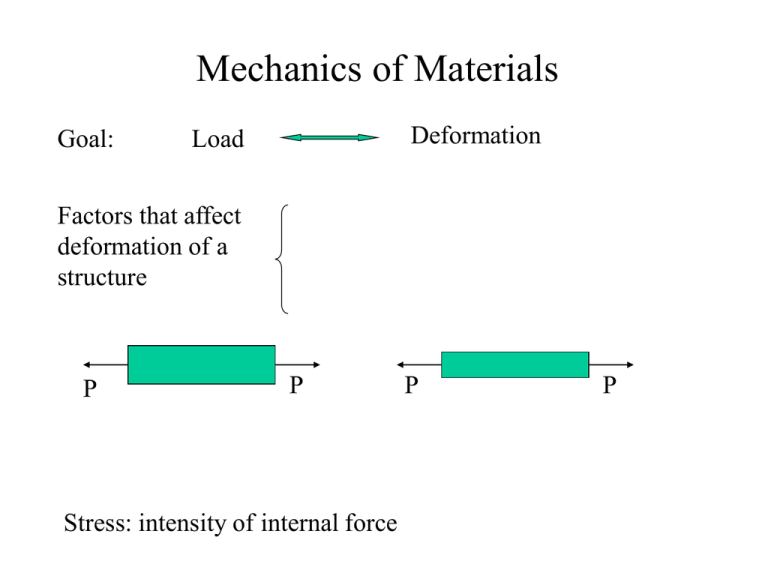
Mechanics of Materials Goal: Deformation Load Factors that affect deformation of a structure P P Stress: intensity of internal force P P Normal Stress (s) Definition: stresses that act in a direction perpendicular to the cut surface s s n n P P tensile stresses (+) Uniformly distributed stresses: compressive stresses (-) P s A P: normal force acting at the cut surface A: cross sectional area Non-uniformly distributed stresses: P s lim A0 A Normal Stress – Example 1 Find stresses at cross sections AA and BB. The cross sectional areas of AA and BB are SAA and SBB respectively. A P1 B P2 A P3 B Deformation and Normal Strain change in size Deformation: change in shape L0 L Lo L Lo P P L Normal Strain: Strain at one point: Lo lim L 0 L Normal Strain – Example 2 Find the total deformation of the structure shown below if the values in the strain gauges are 1 100106 , 2 200106 and L1 100mm, L2 100mm strain gauge 1 P1 P2 strain gauge 2 P3 L1 L2 Stress-Strain Relationship Review: load stress deformation strain Constitutive Law - Stress and Strain Relationship Tensile Test: - Apply load - Measure strain - Plot stress vs. strain curve Stress - Stain Diagram - Ductile Material (structural steel) True Diagram Partially Enlarge Diagram • Proportional limit • Yield stress • Ultimate stress Stress - Stain Diagram - Ductile Material Proportional Limit: the largest value of stress for which Hooke’s law may be applied for a given material. Yield Point s): a critical point, after the yield point, the specimen undergoes a large deformation with a relatively small increase in the applied load. Plastic Deformation: deformation that remains after the load is applied. Ultimate Stress (s): the maximum stress developed in a material before rupture. Breaking Stress (s): stress at rupture. Stress - Strain Diagram - Aluminum Alloy - no noticeable yield point - offset method - yield occurs at 0.2% offset. Stress - Strain Diagram - Brittle Material - rupture occurs without noticeable any prior change in the rate of elongation. - no difference between and . Linear Elasticity Hooke’s Law: s E Poisson’s ratio: the ratio of the lateral or perpendicular strain to the longitudinal or axial strain. lateral strain axial strain Stress-Strain Relationship – Example 3 Find the total deformation of the structure shown below. Express the answer in terms of P’s, S’s, L’s and E. P2 P1 P3 L1 L2 Shear Stress V V Shear force: force that acts tangential to the surface. Average shear stress: V A Shear Stress - double shear F.B.D. of bolt V P 2P , d is the diameter of the bolt A 2 1d2 d2 4 Fb P s , h is the thickness of the clevis Bearing stress: b Ab 2d h Shear stress: ©2001 Brooks/Cole, a division of Thomson Learning, Inc. Thomson Learning™ is a trademark used herein under license. Shear Stress - single shear Shear stress: V P 4P , d is the diameter of the bolt A 1d2 d2 4 Bearing stress: F.B.D. of bolt sb ©2001 Brooks/Cole, a division of Thomson Learning, Inc. Thomson Learning™ is a trademark used herein under license. Fb P , Ab d h h is the thickness of the bar or flange Shear Strain d V L Shear strain: changes in shape (angle). 2 d tan If deformation is small, i.e., is small, L Sign Conventions for Shear Stress Positive faces: outward normal direction is in the positive direction of a coordinate axis. Negative faces: the opposite faces y on a positive face, acts in the positive direction of one of the coordinate axes. x z Positive shear stress: on a negative face, acts in the negative direction of one of the coordinate axes. on a positive face, acts in the negative direction of one of the coordinate axes. Negative shear stress: on a negative face, acts in the positive direction of one of the coordinate axes. Sign Conventions for Shear Strain Positive shear strain: If the angle between two positive faces (or two negative faces) are reduced. Negative shear stress: If the angle between two positive faces (or two negative faces) are increased. Shear Stress vs. Strain - Hooke’s Law in Shear G G: shear modulus or modulus of rigidity Shear Stress and Strain – Example 4 A punch for making holes in steel plates is shown in the following figure. Assume that a punch having diameter d = 20 mm. is used to punch a hole in a 8 mm. plate, as shown in the cross-sectional view. If a force P = 110kN is required to create the hole, what is the average shear stress in the plate and the average compressive stress in the punch?
