Sources of magnetic fields
advertisement
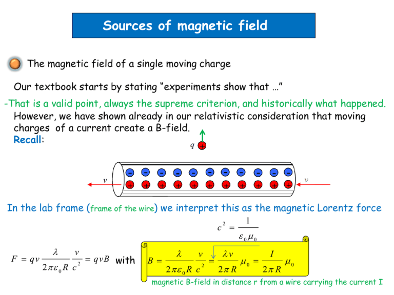
Sources of magnetic field The magnetic field of a single moving charge Our textbook starts by stating “experiments show that …” -That is a valid point, always the supreme criterion, and historically what happened. However, we have shown already in our relativistic consideration that moving charges of a current create a B-field. Recall: In the lab frame (frame of the wire) we interpret this as the magnetic Lorentz force c 2 F qv v 2 0 R c 2 qvB with B v 2 0 R c 2 v 2 R 1 00 0 I 2 R 0 magnetic B-field in distance r from a wire carrying the current I Next we show: the field of the straight wire can be understood in terms of the sum of the contributions from individual moving charges The field of a moving charge measured in P at r from the moving charge reads qv r B 0 3 4 r For an infinitesimal small charge dq we get dl 0 dq v r 0 dq dt r dB 3 3 4 r 4 r R dl r dq dl r 0 dt 3 4 r I 0 d l r 4 r 3 P B dB I 0 4 I 0 4 r sin ( l ) r R (R l ) 2 2 3/ 2 3 dl dl I 0 4 I 0 2 4 R R (R l ) I 0 2 2 3/ 2 dl 2 R As we have shown before in the relativistic consideration Auxiliary consideration (keep practicing): R (R l ) 2 2 3/2 1 dl R 2 1 (1 l / R ) 2 3/2 dl With substitution sinh x= l/R dl R cosh x dx 1 R 2 1 R With 1 R R cosh x (1 sinh x ) 2 3/2 dx http://en.wikipedia.org/wiki/File:Sinh_cosh_tanh.svg cosh x (cosh x sinh x sinh x ) d 2 2 d sinh x tanh x dx 2 2 cosh x dx 1 R tanh x dx R 2 cosh x sinh x cosh x 2 R dx dx 2 cosh x 2 2 dx cosh x dx 3/2 1 1 2 cosh x Biot-Savart law The vector magnetic field expression for the infinitesimal current element dB I 0 d l r 4 r 3 is known as law of Biot and Savart It can be used to find the B-field at any point in space by and arbitrary current in a circuit B I 0 d l r 4 r 3 Biot and Savart law Let’s consider an important example Magnetic field of a circular current loop at a distance x from the center How do we know this is Due to I 0 d l r dB 4 r 3 dB r Or you calculate for this particular element: d l dl e z dlr r r sin , cos , 0 ex ey ez 0 0 dl r dl cos e x r dl sin e y r sin r cos We take advantage of the symmetry to conclude: The y-components of the B-field cancel out 0 dB x I 0 dl r cos 4 r 3 dB x dB x I 0 dl cos 4 r I 0 with 2 dl a x 4 2 a 2 3/2 r a x 2 Bx 2 dB x and 2 I 0 4 a / r c os 2 a x a 2 2 2 3/2 I 0 2 a 2 x a 2 2 3/2 For a thin coil of N loops we get for the magnetic field on the coil axis Bx I 0 2 N a x 2 a 2 2 3/2 and specifically at the center x=0 Bx I 0 N 2 a We can also express the field in terms of the recently introduced magnetic moment Magnetic moment of N loops Bx 0 2 N I a x a 2 2 2 3/2 Application of Bio-Savat law for potential future fusion technology See http://www.pnas.org/content/105/37/13716.full.pdf+html for complete article ITER (International Thermonuclear Experimental Reactor) based on tokamak concept https://www.iter.org/mach Video from February 2014 on ITER HSX (Helically Symmetric eXperiment) @Univ. of Wisconsin-Madison Modular coil stellarator Diagram of the QAS2 stellarator color map of the plasma surface 12 coils produce a magnetic field designed to confine the plasma in equilibrium. Garabedian P R PNAS 2008;105:13716-13719 Four of 12 modular coils that produce the magnetic field of the QAS2 stellarator using the Biot–Savart law. Ampere’s law Similar to the simplified calculation of electric fields of charge distributions using Gauss’ law we can often find a simplified way to calculate magnetic fields of currents Biot-Savart works always but integration can be tough In electric case we could use Gauss’ law Magnetic Gauss law Bd A 0 Q Ed A 0 not so useful Let’s explore what a line integral can do In the electric case What about Bd r ? Ed r 0 because E conservative Let’s consider magnetic field caused by a long, straight conductor B 0 I 2 r et We chose as integration path the path of the field line Bd r 0I 2 r e td r 0 I 2 r 2 r 0I 2 r e t e t dr 0I 2 r dr 0 I Line integral just depends on the enclosed current (not on r… ) What if the integration path does not enclose the current ? We consider this example (result holds in general see textbook) Bd r Bd r Bd r Bd r Bd r a b b c d d a c a 0I 2 r1 r1d 0 0I 2 r2 0 r2 d 0I 2 Bd r Bd r b 0I 2 c d 0 Last step of generalization What a positive or a negative current is with respect to the integration path is determined by the right hand rule Curl fingers of right hand around integration path Arbitrary closed path around conductors Thumb defines direction of positive current Bd r 0 I encl Ampere’s law Remark: Often you find in the literature Ampere’s law written in term of the H-field magnetization H d r I encl In vacuum the relation between B and H is simple B 0 H When the fields in matter are considered situation more complex B 0 H M Let’s apply Ampere’s law (we use the B-field version for now) Of course we could use it to determine the B-field of a long straight wire Bd r 0 I Bd r 2 rB 0 I Radial symmetry of B-field is input B 0 I 2 r B-field inside a long straight wire Bd r 2 rB 0 j r 0 2 B 0 Ir 2 R 2 I R r 0 2 2 Ir 2 R 2 B-field of a long solenoid Field is homogeneous inside a central part Let’s have a look to a central part of the solenoid Bd r Bd r a with n=N/L number of turn per unit length BL 0 NI b B 0 nI Clicker question What can you say about the relation between the direction of the B-field in the solenoid and the direction of the magnetic dipole moment? 1) There is no relation 2) They point in the same direction 3) They are antiparallel 4) They are orthogonal 5) They make angle of cos-1B
