GPUs - Electronic Systems group
advertisement
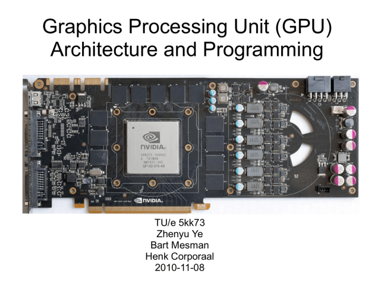
Graphics Processing Unit (GPU)
Architecture and Programming
TU/e 5kk73
Zhenyu Ye
Bart Mesman
Henk Corporaal
2010-11-08
Today's Topics
•
•
•
•
•
GPU architecture
GPU programming
GPU micro-architecture
Performance optimization and model
Trends
Today's Topics
•
•
•
•
•
GPU architecture
GPU programming
GPU micro-architecture
Performance optimization and model
Trends
System Architecture
GPU Architecture
NVIDIA Fermi, 512 Processing Elements (PEs)
What Can It Do?
Render triangles.
NVIDIA GTX480 can render 1.6
billion triangles per second!
General Purposed Computing
ref: http://www.nvidia.com/object/tesla_computing_solutions.html
The Vision of NVIDIA
"Within the next few years, there will be single-chip graphics
devices more powerful and versatile than any graphics
system that has ever been built, at any price."
-- David Kirk, NVIDIA, 1998
Single-Chip GPU v.s. Fastest Super Computers
ref: http://www.llnl.gov/str/JanFeb05/Seager.html
Top500 Super Computer in June 2010
GPU Will Top the List in Nov 2010
The Gap Between CPU and GPU
ref: Tesla GPU Computing Brochure
GPU Has 10x Comp Density
Given the same chip area, the achievable performance of
GPU is 10x higher than that of CPU.
Evolution of Intel Pentium
Pentium I
Pentium II
Chip area
breakdown
Pentium III
Q: What can you observe? Why?
Pentium IV
Extrapolation of Single Core CPU
If we extrapolate the trend, in a few generations, Pentium
will look like:
Of course, we know it did not happen.
Q: What happened instead? Why?
Evolution of Multi-core CPUs
Penryn
Chip area Bloomfield
breakdown
Gulftown
Q: What can you observe? Why?
Beckton
Let's Take a Closer Look
Less than 10% of total chip area is used for the real execution.
Q: Why?
The Memory Hierarchy
Notes on Energy at 45nm:
64-bit Int ADD takes about 1 pJ.
64-bit FP FMA takes about 200 pJ.
It seems we can not further increase the computational density.
The Brick Wall -- UC Berkeley's View
Power Wall: power expensive, transistors free
Memory Wall: Memory slow, multiplies fast
ILP Wall: diminishing returns on more ILP HW
David Patterson, "Computer Architecture is Back - The Berkeley View of the Parallel Computing Research Landscape", Stanford EE
Computer Systems Colloquium, Jan 2007, link
The Brick Wall -- UC Berkeley's View
Power Wall: power expensive, transistors free
Memory Wall: Memory slow, multiplies fast
ILP Wall: diminishing returns on more ILP HW
Power Wall + Memory Wall + ILP Wall = Brick Wall
David Patterson, "Computer Architecture is Back - The Berkeley View of the Parallel Computing Research Landscape", Stanford EE
Computer Systems Colloquium, Jan 2007, link
How to Break the Brick Wall?
Hint: how to exploit the parallelism inside the application?
Step 1: Trade Latency with Throughput
Hind the memory latency through fine-grained interleaved
threading.
Interleaved Multi-threading
Interleaved Multi-threading
The granularity of interleaved multi-threading:
• 100 cycles: hide off-chip memory latency
• 10 cycles: + hide cache latency
• 1 cycle: + hide branch latency, instruction dependency
Interleaved Multi-threading
The granularity of interleaved multi-threading:
• 100 cycles: hide off-chip memory latency
• 10 cycles: + hide cache latency
• 1 cycle: + hide branch latency, instruction dependency
Fine-grained interleaved multi-threading:
Pros: ?
Cons: ?
Interleaved Multi-threading
The granularity of interleaved multi-threading:
• 100 cycles: hide off-chip memory latency
• 10 cycles: + hide cache latency
• 1 cycle: + hide branch latency, instruction dependency
Fine-grained interleaved multi-threading:
Pros: remove branch predictor, OOO scheduler, large cache
Cons: register pressure, etc.
Fine-Grained Interleaved Threading
Without and with fine-grained interleaved threading
Pros:
reduce cache size,
no branch predictor,
no OOO scheduler
Cons:
register pressure,
thread scheduler,
require huge parallelism
HW Support
Register file supports zero
overhead context switch
between interleaved
threads.
Can We Make Further Improvement?
Reducing large cache gives 2x computational density.
Q: Can we make further improvements?
Hint:
We have only utilized thread
level parallelism (TLP) so far.
Step 2: Single Instruction Multiple Data
GPU uses wide SIMD: 8/16/24/... processing elements (PEs)
CPU uses short SIMD: usually has vector width of 4.
SSE has 4 data lanes
GPU has 8/16/24/... data lanes
Hardware Support
Supporting interleaved threading + SIMD execution
Single Instruction Multiple Thread (SIMT)
Hide vector width using scalar threads.
Example of SIMT Execution
Assume 32 threads are grouped into one warp.
Step 3: Simple Core
The Stream Multiprocessor (SM) is a
light weight core compared to IA core.
Light weight PE:
Fused Multiply Add
(FMA)
SFU:
Special Function
Unit
NVIDIA's Motivation of Simple Core
"This [multiple IA-core] approach is analogous to trying to
build an airplane by putting wings on a train."
--Bill Dally, NVIDIA
Review: How Do We Reach Here?
NVIDIA Fermi, 512 Processing Elements (PEs)
Throughput Oriented Architectures
1. Fine-grained interleaved threading (~2x comp density)
2. SIMD/SIMT (>10x comp density)
3. Simple core (~2x comp density)
Key architectural features of throughput oriented processor.
ref: Michael Garland. David B. Kirk, "Understanding throughput-oriented architectures", CACM 2010. (link)
Today's Topics
•
•
•
•
•
GPU architecture
GPU programming
GPU micro-architecture
Performance optimization and model
Trends
CUDA Programming
Massive number (>10000) of light-weight threads.
Express Data Parallelism in Threads
Compare thread program with vector program.
Vector Program
Vector width is exposed to programmers.
Vector program (vector width of 8)
Scalar program
float A[4][8];
do-all(i=0;i<4;i++){
do-all(j=0;j<8;j++){
A[i][j]++;
}
}
float A[4][8];
do-all(i=0;i<4;i++){
movups xmm0, [ &A[i][0] ]
incps xmm0
movups [ &A[i][0] ], xmm0
}
CUDA Program
• CUDA program expresses data level parallelism (DLP) in
terms of thread level parallelism (TLP).
• Hardware converts TLP into DLP at run time.
CUDA program
Scalar program
float A[4][8];
do-all(i=0;i<4;i++){
do-all(j=0;j<8;j++){
A[i][j]++;
}
}
float A[4][8];
kernelF<<<(4,1),(8,1)>>>(A);
__device__ kernelF(A){
i = blockIdx.x;
j = threadIdx.x;
A[i][j]++;
}
Two Levels of Thread Hierarchy
kernelF<<<(4,1),(8,1)>>>(A);
__device__ kernelF(A){
i = blockIdx.x;
j = threadIdx.x;
A[i][j]++;
}
Multi-dimension Thread and Block ID
Both grid and thread block can have two dimensional index.
kernelF<<<(2,2),(4,2)>>>(A);
__device__ kernelF(A){
i = blockDim.x * blockIdx.y
+ blockIdx.x;
j = threadDim.x * threadIdx.y
+ threadIdx.x;
A[i][j]++;
}
Scheduling Thread Blocks on SM
Example:
Scheduling 4 thread blocks on 3 SMs.
Executing Thread Block on SM
kernelF<<<(2,2),(4,2)>>>(A);
__device__ kernelF(A){
i = blockDim.x * blockIdx.y
+ blockIdx.x;
j = threadDim.x * threadIdx.y
+ threadIdx.x;
A[i][j]++;
}
Notes: the number of
Processing Elements
(PEs) is transparent to
programmer.
Executed on machine with width of 4:
Executed on machine with width of 8:
Multiple Levels of Memory Hierarchy
Name
Cache? cycle
read-only?
Global
L1/L2
200~400 (cache miss) R/W
Shared
Constant
Texture
Local
No
Yes
Yes
L1/L2
1~3
1~3
~100
200~400 (cache miss)
R/W
Read-only
Read-only
R/W
Explicit Management of Shared Mem
Shared memory is frequently used to exploit locality.
Shared Memory and Synchronization
Example: average filter with
3x3 window
3x3 window on image
kernelF<<<(1,1),(16,16)>>>(A);
__device__ kernelF(A){
__shared__ smem[16][16]; //allocate smem
i = threadIdx.y;
j = threadIdx.x;
Image
smem[i][j] = A[i][j];
__sync();
A[i][j] = ( smem[i-1][j-1]
+ smem[i-1][j]
...
+ smem[i+1][i+1] ) / 9;
}
data in DRAM
Shared Memory and Synchronization
Example: average filter over
3x3 window
3x3 window on image
kernelF<<<(1,1),(16,16)>>>(A);
__device__ kernelF(A){
__shared__ smem[16][16];
i = threadIdx.y;
j = threadIdx.x;
smem[i][j] = A[i][j]; // load to smem
__sync(); // thread wait at barrier
A[i][j] = ( smem[i-1][j-1]
+ smem[i-1][j]
...
+ smem[i+1][i+1] ) / 9;
}
Stage data in shared mem
Shared Memory and Synchronization
Example: average filter over
3x3 window
3x3 window on image
kernelF<<<(1,1),(16,16)>>>(A);
__device__ kernelF(A){
__shared__ smem[16][16];
i = threadIdx.y;
j = threadIdx.x;
smem[i][j] = A[i][j];
__sync(); // every thread is ready
A[i][j] = ( smem[i-1][j-1]
+ smem[i-1][j]
...
+ smem[i+1][i+1] ) / 9;
}
all threads finish the load
Shared Memory and Synchronization
Example: average filter over
3x3 window
3x3 window on image
kernelF<<<(1,1),(16,16)>>>(A);
__device__ kernelF(A){
__shared__ smem[16][16];
i = threadIdx.y;
j = threadIdx.x;
smem[i][j] = A[i][j];
__sync();
A[i][j] = ( smem[i-1][j-1]
+ smem[i-1][j]
...
+ smem[i+1][i+1] ) / 9;
}
Start computation
Programmers Think in Threads
Q: Why make this
hassle?
Why Use Thread instead of Vector?
Thread Pros:
• Portability. Machine width is transparent in ISA.
• Productivity. Programmers do not need to take care the
vector width of the machine.
Thread Cons:
• Manual sync. Give up lock-step within vector.
• Scheduling of thread could be inefficient.
• Debug. "Threads considered harmful". Thread program
is notoriously hard to debug.
Features of CUDA
• Programmers explicitly express DLP in terms of TLP.
• Programmers explicitly manage memory hierarchy.
• etc.
Today's Topics
•
•
•
•
•
GPU architecture
GPU programming
GPU micro-architecture
Performance optimization and model
Trends
Micro-architecture
GF100 micro-architecture
HW Groups Threads Into Warps
Example: 32 threads per warp
Example of Implementation
Note: NVIDIA may use a more
complicated implementation.
Example
Program Address: Inst
0x0004: add r0, r1, r2
0x0008: sub r3, r4, r5
Assume warp 0 and
warp 1 are scheduled
for execution.
Read Src Op
Program Address: Inst
0x0004: add r0, r1, r2
0x0008: sub r3, r4, r5
Read source operands:
r1 for warp 0
r4 for warp 1
Buffer Src Op
Program Address: Inst
0x0004: add r0, r1, r2
0x0008: sub r3, r4, r5
Push ops to op collector:
r1 for warp 0
r4 for warp 1
Read Src Op
Program Address: Inst
0x0004: add r0, r1, r2
0x0008: sub r3, r4, r5
Read source operands:
r2 for warp 0
r5 for warp 1
Buffer Src Op
Program Address: Inst
0x0004: add r0, r1, r2
0x0008: sub r3, r4, r5
Push ops to op collector:
r2 for warp 0
r5 for warp 1
Execute
Program Address: Inst
0x0004: add r0, r1, r2
0x0008: sub r3, r4, r5
Compute the first 16
threads in the warp.
Execute
Program Address: Inst
0x0004: add r0, r1, r2
0x0008: sub r3, r4, r5
Compute the last 16
threads in the warp.
Write back
Program Address: Inst
0x0004: add r0, r1, r2
0x0008: sub r3, r4, r5
Write back:
r0 for warp 0
r3 for warp 1
Other High Performance GPU
• ATI Radeon 5000 series.
ATI Radeon 5000 Series Architecture
Radeon SIMD Engine
• 16 Stream Cores (SC)
• Local Data Share
VLIW Stream Core (SC)
Local Data Share (LDS)
Today's Topics
•
•
•
•
•
GPU architecture
GPU programming
GPU micro-architecture
Performance optimization and model
Trends
Performance Optimization
Optimizations on memory latency tolerance
• Reduce register pressure
• Reduce shared memory pressure
Optimizations on memory bandwidth
• Global memory coalesce
• Avoid shared memory bank conflicts
• Grouping byte access
• Avoid Partition camping
Optimizations on computation efficiency
• Mul/Add balancing
• Increase floating point proportion
Optimizations on operational intensity
• Use tiled algorithm
• Tuning thread granularity
Shared Mem Contains Multiple Banks
Compute Capability
Need arch info to
perform optimization.
ref: NVIDIA, "CUDA C Programming Guide", (link)
Shared Memory (compute capability 2.x)
without
bank
conflict:
with
bank
conflict:
Performance Optimization
Optimizations on memory latency tolerance
• Reduce register pressure
• Reduce shared memory pressure
Optimizations on memory bandwidth
• Global memory alignment and coalescing
• Avoid shared memory bank conflicts
• Grouping byte access
• Avoid Partition camping
Optimizations on computation efficiency
• Mul/Add balancing
• Increase floating point proportion
Optimizations on operational intensity
• Use tiled algorithm
• Tuning thread granularity
Global Memory In Off-Chip DRAM
Address space is interleaved among multiple channels.
Global Memory
Global Memory
Global Memory
Roofline Model
Identify performance bottleneck:
computation bound v.s. bandwidth bound
Optimization Is Key for Attainable Gflops/s
Computation, Bandwidth, Latency
Illustrating three bottlenecks in the Roofline model.
Today's Topics
•
•
•
•
•
GPU architecture
GPU programming
GPU micro-architecture
Performance optimization and model
Trends
Trends
Coming architectures:
• Intel's Larabee successor: Many Integrated Core (MIC)
• CPU/GPU fusion, Intel Sandy Bridge, AMD Llano.
Intel Many Integrated Core (MIC)
32 core version of MIC:
Intel Sandy Bridge
Highlight:
• Reconfigurable shared L3
for CPU and GPU
• Ring bus
Sandy Bridge's New CPU-GPU interface
ref: "Intel's Sandy Bridge Architecture Exposed", from Anandtech, (link)
Sandy Bridge's New CPU-GPU interface
ref: "Intel's Sandy Bridge Architecture Exposed", from Anandtech, (link)
AMD Llano Fusion APU (expt. Q3 2011)
Notes:
• CPU and GPU are not
sharing cache?
• Unknown interface
between CPU/GPU
GPU Research in ES Group
GPU research in the Electronic Systems group.
http://www.es.ele.tue.nl/~gpuattue/


