Salem S. Ghozzi
advertisement
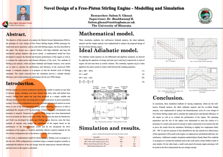
Novel Design of a Free-Piston Stirling Engine - Modelling and Simulation Researcher: Salem S. Ghozzi Supervisor: Dr. Boukhanouf R. Salem.ghozzi@nottingham.ac.uk The University of Misurata Abstract. Mathematical model. The objective of this research is to employ the Particle Swarm Optimization (PSO) to Three simulation methods, the well-known Schmidt analysis, the ideal adiabatic the principle of a new design of Free Piston Stirling Engine (FPSE) prototype for analysis and the simple analysis were implemented to analyze the proposal design of small-scale power generator, such as solar dish Stirling engine, has been described in the Free-Piston Stirling engine. this paper. The design uses a special bellows with high reliability and long life mechanical springs displacer and power piston. A mathematical model has been Ideal Adiabatic model. developed to analyze the thermal and dynamic performance of the engine as well as The adiabatic model equation set, the differential and algebraic equations, are derived to evaluate the output power and thermal efficiency of the cycle. Two methods of by applying the equations of energy and state (eq.1) and (eq.2) respectively to each of Stirling cycle analysis, which are Ideal Adiabatic and Simple Analysis, were carried engine cell and treat them as control volumes. The continuity equation (eq.3) is then out in order to calculate the performance and efficiency of the conserved FPSE applied to the entire system to create a link between the resulting equations. design. A computer program is in progress so that the thermal cycle of Stirling 𝑑𝑄 = 𝑑𝑊 − 𝑅𝑇𝑚 (1) simulated. The results extracted from the simulation proved a valuable thermal 𝑃𝑉 = 𝑚𝑅𝑇 (2) efficiency and overall satisfactory performance for the new FPSE design. 𝑑𝑚 = 𝑔𝐴𝑖 − 𝑔𝐴𝑜 (3) 𝑑𝑃 𝑃 (4) Introduction. + 𝑑𝑉 𝑉 = 𝑑𝑚 𝑚 + 𝑑𝑇 𝑇 Stirling engines are external combustion machine that enable to operate on any kind Fig 5. . Temperature gradient in the engine cells with the crank angle of thermal energy including west heat, thermal heat from solar and biofuel heat Fig. 4. Cyclic energy with the crank angle Fig. 6. Mass flow rate in the engine cells with the crank angle Conclusion. sources. Stirling heat engine has long been proposed as a simple, reliable and efficient prime mover that converting heat to mechanical power in power generation systems. Free piston configuration receiving a considerable research interest in recent Fig 3. PV diagram Fig. 1 The indicated variables for the Ideal Adiabatic approach In conclusion, three simulation methods of varying complexity, which are the well- times, as one of the most promising Stirling cycle technology. However, so that to known Schmidt analysis, the Ideal Adiabatic analysis and the so-called Simple understand the concept of FP the knowledge of thermodynamics aerodynamics and analysis, were implemented to analyze the thermodynamic cycle of a new design of dynamics is required. Numerous advances in FPSE design have been demonstrated Free-Piston Stirling engine and to calculate the output power and thermal efficiency of since its invention by Beale in the early 1960s. The analysis has done by Berchowitz the engine as well as to evaluate the performance of the engine. The operating and Urieli was developed for alpha type Stirling engine, however, since the these parameters and the size of the engine were determined to meet the criteria of a Fig. 2. Temperature gradient - Ideal adiabatic model. methods of analysis only predict the capabilities of the engine based on the performance of the thermodynamic cycles and do not incorporate the drive mechanism of the engine, it would be absolutely effective analysis methods for the Free-Piston configuration due to the absence of any the drive mechanisms. In this work, a mathematical model for thermodynamic Stirling cycle in progress so that the new FPSE configuration is simulated using a computer program certainly to understand the behavior of the new design, thus the output power, thermal efficiency and heat losses in the engine is calculated. Simulation and results. Value 50 300 2 20 to prove the results from the simulation. Referring to slightly low temperature limits (50 – 300 °C) and low pressure (2 bar) identified by the user and the low effectiveness of the regenerator (10%) used in the engine, its output power and thermal efficiency are TABLE I: OPERATING PARAMETERS FOR THE SIMULATION Variable Cold side wall temperature (Tk) Hot side wall temperature (Th) Mean operating pressure (Pmean) Operating frequency (f) prototype of a small scale proof-of-concept is under construction to be tested in the lab Unit °C °C bar Hz satisfactory. Additional complex simulation method (Quasi Steady-State Flow method) is in progress to evaluate the methods used in this work and to extract further results in more details. On the other hand, a small scale proof-of-concept engine prototype will be tested in the lab to demonstrate the new design concept.
