SPCC Rule Amendments - National Response Team
advertisement
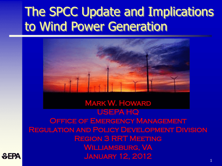
The SPCC Update and Implications to Wind Power Generation Mark W. Howard USEPA HQ Office of Emergency Management Regulation and Policy Development Division Region 3 RRT Meeting Williamsburg, VA January 12, 2012 1 Agenda SPCC Update and Implications to Wind Power Generation Virginia 2011 Earthquake Implications on AST Integrity and What to Look for in the Field 2 Please note that this presentation is a summary and does not cover every SPCC provision Always refer to the SPCC rule and official Agency guidance found at www.epa.gov/oilspill 3 Overview of Wind Farming 4 History of Wind Energy • Wind energy propelled boats along the Nile River as early as 5000 B.C. • By 200 B.C., simple windmills in China were pumping water • The Dutch refined the windmill and adapted it for draining lakes and marshes • Settlers took this technology to the New World and began using windmills to pump water for farms and ranches • Industrialization led to a gradual decline in the use of windmills • Industrialization also sparked the development of larger windmills to generate electricity. Commonly called Wind Turbines Generators (WTGs) • The popularity of using the energy in the wind has always fluctuated with the price of fossil fuels • Lessons learned from more than a decade of operating wind power plants, and continuing R&D, have made wind-generated electricity cost effective • Wind energy is the world's fastest-growing energy source 5 DOE Forecasting of Wind Power 6 Region 3 and Wind Power http://www.awea.org/learnabout/publications/factsheets/factsheets_state.cfm 7 Growth in Region 3 http://www.awea.org/learnabout/publications/reports/index.cfm 8 Parts of the Wind Farm http://reich-chemistry.wikispaces.com/Benoit.Quinn.Fall.2009.energywiki 9 Wind Turbine Generators http://wind-turbine.tripod.com/id13.html 10 Wind Turbine Generators http://www.windpowerninja.com/wpcontent/uploads/2009/04/wind-turbine-parts.jpg 11 Wind Turbine Generator Tower http://reichchemistry.wikispaces.com/file/view/insideturbine.jpg/18 4820427/insideturbine.jpg http://cleangreenenergyzone.com/wpcontent/uploads/2011/03/wind-turbinetransformer.jpg 12 Wind Turbine Generator Size Comparisons http://www.four-winds-energy.com/Relative%20sizes.jpg 13 The SPCC Rule and Implications to Wind Farming 14 What is the SPCC Rule? Spill Prevention, Control, and Countermeasure rule Part of the Oil Pollution Prevention regulation (40 CFR part 112) – Includes requirements for Facility Response Plans (FRPs) for certain facilities which pose a greater threat to waterways and the environment Purpose – To develop plans designed to prevent oil discharges from reaching the navigable waters of the U.S. and adjoining shorelines 15 Spill Prevention, Control and Countermeasure (SPCC) Rule Overview Authority from Clean Water Act Oil Pollution Prevention regulation codified at 40 CFR part 112 Original rule effective in January 1974 Non-delegable to other agencies 16 SPCC Applicability Owner/operator makes the initial decision on applicability of SPCC regulations to the facility – Does the facility meet the applicability criteria (volumes of oil, expectation to spill to waterway)? No requirement to submit SPCC Plan to EPA for approval EPA does not formally “approve” or disapprove of SPCC Plan Plan is required upon inspection during regular workday 17 General SPCC Rule Applicability The SPCC Rule applies to a facility that meets the following criteria: 1 Drills, produces, gathers, stores, processes, refines, transfers, distributes, uses, or consumes 2 oil and oil products; and 3 Is non-transportation related (i.e. facility is not exclusively covered by DOI or DOT); and 4 5 Can reasonably be expected to discharge oil in quantities that may be harmful into or upon the navigable waters of the U.S. or adjoining shorelines; and Meets capacity thresholds • Aboveground storage > 1,320 gallons; or • Completely buried storage > 42,000 gallons 18 Facility Facility- any mobile or fixed, onshore or offshore building, property, parcel, lease, structure, installation, equipment, pipe, or pipeline (other than a vessel or a public vessel) used in oil well drilling operations, oil production, oil refining, oil storage, oil gathering, oil processing, oil transfer, oil distribution, and oil waste treatment, or in which oil is used, as described in Appendix A to this part. The boundaries of a facility depend on several site-specific factors, including but not limited to, the ownership or operation of buildings, structures, and equipment on the same site and types of activity at the site. Contiguous or non-contiguous buildings, properties, parcels, leases, structures, installations, pipes, or pipelines under the ownership or operation of the same person may be considered separate facilities. Only this definition governs whether a facility is subject to this part. 19 What the definition means… According to EPA guidance, the extent of a “facility” depends on site-specific circumstances: - Ownership, management, and operation of the buildings, structures, equipment, installations, pipes, or pipelines on the site; - Similarity in functions, operational characteristics, and types of activities occurring at the site; - Adjacency; or - Shared drainage pathways (e.g., same receiving water bodies). 20 Jurisdiction Issues • Appendix B to the 40 CFR part 112 • Pursuant to section 2(i) of E.O. 12777, DOI redelegates, and EPA and DOT agree to assume, the functions vested in DOI by sections 2(b)(3), 2(d)(3), and 2(e)(3) of E.O. 12777 as set forth below. • For purposes of this MOU, the term “coast line” shall be defined as in the Submerged Lands Act (43 U.S.C.1301(c)) to mean “the line of ordinary low water along that portion of the coast which is in direct contact with the open sea and the line marking the seaward limit of inland waters.” • To EPA, DOI redelegates responsibility for non-transportationrelated offshore facilities located landward of the coast line. 21 SPCC Rule Exemptions • Containers with a capacity <55 gallons* • Facilities subject solely to other agency jurisdictions • Underground storage tanks subject to UST technical requirements • USTs at nuclear power generation facilities • Wastewater treatment facilities • Permanently closed containers • Motive power containers • Hot-mix asphalt (HMA) • Residential heating oil containers (ASTs and USTs) • Pesticide application equipment • Intra-facility gathering lines subject to the requirements of 49 CFR part 192 or 195 • Milk and milk product containers and associated piping and appurtenances §112.1(d) * Exemptions in yellow may apply and wind power generation facilities 22 Definitions - Oil Oil, as defined in Section 311 (a)(1) of the CWA, can be of any kind or in any form including, but not limited to - Petroleum and non- - petroleum based oils - Crude Oil - Refined Products and - Vegetable oils For Wind Farms - Dielectric oils - Lube oils - Hydraulic oils 23 Key SPCC Requirements Prepare Plan in accordance with Good Engineering Practices Full approval of management to implement Plan Follow sequence of Section 112.7, or use a cross-reference section 112.7 has a number of new response oriented provisions 24 SPCC Key Requirements SPCC regulations requires preparation and implementation of a written Plan to address: – Operating procedures for routine handling of products to prevent a discharge of oil – Discharge or drainage control measures to prevent a discharge of oil – Countermeasures to contain, clean up, and mitigate an oil spill – Methods of disposal of recovered materials – Contact list and phone numbers of company, contract response personnel, and National Response Center 25 Typical SPCC Plan for Utility Wind Energy Center • The Ormes & Lillard Wind Energy Center is a 99-Megawatt electrical power generating facility • The site consists of sixty-six (66) Wind Turbine Generators (WTG’s), each with a nameplate capacity of 1.5 Megawatts. • The WTG’s are located on private property, typically pasture or corn fields • Oil is used in the WTG’s gearbox, hydraulic system, and cooling system for operational purposes. • The WTG’s each have a pad mounted electrical transformer that sits on the ground near the base of the tower. The transformers also use oil operationally as a coolant to dissipate heat. • Each pad mount transformer is connected to a collection system of either underground or overhead electric lines. • The collection system feeds into a single substation that contains a large transformer and grounding transformers, as well as circuit breakers that use oil operationally; again for cooling purposes. • Included in the project area is the operations and maintenance building. This building is the headquarters for the facility’s operations personnel. • The facility is monitored via a complex computer system that is used to monitor and control the operations of each WTG. 26 Typical SPCC Plan for Wind Farm or Wind Energy Center 27 Typical Wind Farm Containers 28 SPCC Rule Key Requirements SPCC Plan must be maintained at facility if manned 4 hours/per day or more, or at nearest field office if manned less than 4 hours/per day Allowance of usual and customary business records to serve as records of inspection or tests 29 Inspections, Tests, and Records Conduct inspections and tests in accordance with written procedures developed by the facility or by the engineer who certifies the facility Plan Keep these written procedures and a record of the inspections and tests, signed by the appropriate supervisor or inspector, with the SPCC Plan for a period of three years 30 Training • Train oil-handling personnel – – – – – Operation/maintenance of prevention equipment Discharge procedure protocols Applicable pollution control laws, rules, and regulations General facility operations Contents of the facility SPCC Plan • Designate person accountable for discharge prevention and who reports to facility management • Schedule/conduct at least one briefing/year: – Known discharges and failures, malfunctioning components, new precautionary measures 31 General Secondary Containment • Provide appropriate secondary containment and/or diversionary structures or equipment to prevent a discharge (from tanks, drums, totes, piping, etc.) to “navigable waters of the U.S. and adjoining shorelines” • The entire system (walls and floor) must be capable of containing oil so that a discharge from containment will not occur until cleanup occurs • §112.7(c) 32 General Secondary Containment One of the following preventive systems or its equivalent should be used as a minimum for onshore facilities: – Dikes, berms or retaining walls sufficiently impervious to contain spilled oil – Curbing or drip pans – Sumps and collection systems – Culverting, gutters or other drainage systems – Weirs, booms or other barriers – Spill diversion ponds – Retention ponds – Sorbent materials 33 Revision to General Secondary Containment Requirement Clarified that the general secondary containment requirement is intended to address the most likely oil discharge from any part of a facility Use of active and passive secondary containment, such as spill kits, allowed New text: “… In determining the method, design, and capacity for secondary containment, you need only to address the typical failure mode, and the most likely quantity of oil that would be discharged. Secondary containment may be either active or passive in design.” Modifies §112.7(c) to expand the list of example prevention systems for onshore facilities – Additional examples: drip pans, sumps, and collection systems 34 General Secondary Containment “General” Secondary Containment requirement applies to the following examples: – Nurse tanks – Mobile refuelers – Oil-filled equipment (transformers, manufacturing equipment, etc.) – Transfer areas Piping runs/racks, manifolds, etc. Truck loading/unloading areas (not loading rack) No specific-sized volume requirement Sizing based on typical spill size not container size 35 Specific Secondary Containment Requirements Specific minimum size requirement for secondary containment for: – Bulk storage containers – Mobile or portable bulk storage containers* The secondary containment must be sized to contain the largest single oil compartment or container plus “sufficient freeboard” to contain precipitation Does not apply to the Wind Turbine and other oil filled equipment * Mobile portable containers which serve as tanker trucks are only required to have general secondary containment 36 Bulk Storage Container Requirements No container should be used for the storage of oil unless its oil and construction are compatible with the oil stored and the conditions of storage, such as pressure and temp., etc. Integrity and inspection requirements Overfill protection requirements Requirements for general secondary containment for non transportation-related tanker trucks Does not apply to the Wind Turbine and other oil filled equipment 37 Oil-Filled Operational Equipment and Wind Farms • Equipment that includes an oil storage container (or multiple containers) in which the oil is present solely to support the function of the apparatus or the device – Not considered a bulk storage container – Does not include oil-filled manufacturing equipment Examples: hydraulic systems, lubricating systems, gear boxes, machining coolant systems, heat transfer systems, transformers, circuit breakers, electrical switches, other systems containing oil solely to enable the operation of the device Oil is used in the WTG’s gearbox, hydraulic system, and cooling system for operational purposes. 38 Qualified Oil-Filled Operational Equipment Alternative to the general secondary containment requirements for qualified oil-filled operational equipment: – Prepare an oil spill contingency Plan and a written commitment of manpower, equipment, and materials – Have an inspection or monitoring program to detect equipment failure and/or a discharge (§112.7(k)) Must meet eligibility criteria 39 Qualified Oil-Filled Operational Equipment Eligibility Criteria For the 3 years prior to Plan certification, or since becoming subject to the Rule if it has operated for less than 3 years, the facility must not have had: – A single §112.1(b) discharge of oil from any oilfilled operational equipment exceeding 1,000 U.S. gallons; or – Two §112.1(b) discharges of oil from any oil-filled operational equipment each exceeding 42 U.S. gallons within any 12-month period. The gallon amount(s) specified (either 1,000 or 42) refers to the amount of oil that actually reaches navigable waters of the U.S. and adjoining shorelines not the total amount of oil spilled. The entire volume of the discharge is oil for the purposes of this reporting requirement. 40 Wind Turbines: Preamble Clarification • Wind turbines meet the definition of oil-filled operational equipment promulgated in the December 2006 SPCC rule amendments. • Can take advantage of the alternative compliance option provided to qualified oilfilled operational equipment, in lieu of secondary containment • The design of the wind turbine may inherently provide sufficient secondary containment for its oil reservoirs • Did not address site specific facility determinations for wind turbines • For more information: – 71 FR 77266 – 73 FR 74294 – 74 FR 58797 41 Qualified Facilities – An Overview A qualified facility is a smaller oil storage facility that is eligible for streamlined regulatory requirements – Self-certified SPCC Plan instead of one reviewed and certified by a Professional Engineer Must meet eligibility criteria This group of facilities divided into two tiers – Tier I - complete a self-certified SPCC Plan following a template – Tier II - prepare and self-certify an SPCC Plan 42 Summary: Qualified Facilities Applicability If the facility total aboveground oil storage capacity is 10,000 gallons or less And… Within three years prior to the Plan certification date, or since becoming subject to the SPCC rule if in operation for less than three years, the facility has not discharged oil to navigable waters of the U.S. and adjoining shorelines in: A single discharge exceeding 1,000 gallons, or Two discharges each exceeding 42 gallons within any 12-month period. And the facility has… No individual aboveground oil containers greater than 5,000 gallons; Any individual aboveground oil container greater than 5,000 gallons; Then the facility is a: Tier I Qualified Facility: Complete and self-certify Plan template (Appendix G of SPCC rule) instead of a full PE-certified Plan or other self-certified SPCC Plan. Tier II Qualified Facility: Prepare a self-certified Plan in accordance with all applicable requirements of §112.7 and subparts B or C of the rule, in lieu of a PEcertified Plan. 43 Qualified Facilities Self-Certification Facilities that meet the eligibility criteria are able to prepare and self-certify an SPCC Plan as Tier II qualified facilities Self-certified SPCC Plans must follow the rule requirements – Cannot deviate from rule requirements UNLESS – A PE certifies the environmentally equivalent alternative and/or contingency plan substituting for secondary containment (“hybrid Plan”- Tier II facilities only) NOTE: Some states require a PE to certify SPCC Plans 44 Tier I Qualified Facilities Option to complete a self-certified SPCC Plan template instead of a full SPCC Plan – A Tier I qualified facility owner/operator can choose to comply with either Tier I or Tier II requirements or prepare a PE-certified Plan in accordance with all applicable requirements of §112.7 and subparts B and C – Template is found in Appendix G to the SPCC rule Template is designed to be a simple SPCC Plan – Cannot be a “hybrid Plan” (i.e., no PE-certified environmental equivalence or contingency plan instead of secondary containment) 45 Current Compliance Dates for Facilities (except farms) A facility starting operation… Must… On or before August 16, 2002 •Maintain existing SPCC Plan •Amend and implement the SPCC Plan no later than November 10, 2011. After August 16, 2002 through November 10, 2011 •Prepare and implement the SPCC Plan no later than November 10, 2011. After November 10, 2011 •Prepare and implement an SPCC Plan before beginning operations. 46 For More Information EPA’s SPCC web page http://www.epa.gov/emergencies/content/spcc/index.htm EPA Oil Spill and Emergency Management web pages www.epa.gov/oilspill www.epa.gov/emergencies HOTLINE: Superfund, TRI, EPCRA, RMP, and Oil Information Center – (800) 424-9346 or (703) 412-9810 – TDD (800) 553-7672 or (703) 412-3323 – www.epa.gov/superfund/resources/infocenter 47 48 Virginia 2011 Earthquake Implications to AST Integrity What to look for in the field 2011 Virginia Earthquake • Occurred on August 23, 2011, at 1:51 pm EDT − Magnitude 5.8 − Epicenter was 38 miles northwest of Richmond − Numerous aftershocks occurred within 12 hours ranging in magnitude up to 4.2 • Is one of the largest earthquakes to have occurred in the U.S. east of the Rocky Mountains since 1897 • The earthquake was felt in more than a dozen U.S. states and in several Canadian provinces 50 Seismic Effects on Aboveground Tanks • Ground motion from earthquakes causes aboveground tanks to rock back and forth and to a lesser degree, move up and down 51 Seismic Effects on Vertical Aboveground Tanks • Rocking action from seismic ground motion can cause tanks to tip over (i.e. overturn) if not anchored to a foundation that has sufficient mass to resist overturning − Tanks that have a shell height greater than their diameter are more susceptible to overturning than short tanks − Tanks with a height to diameter ratio greater than 0.75 are considered tall tanks 52 Seismic Effects on Vertical Aboveground Tanks • Rocking action can also cause a portion of the tank shell to uplift. This uplift in turn creates compression in the shell on the opposite side of the tank. − Excessive compression in the tank shell can result in shell buckling known as “elephant’s foot” 53 Seismic Effects on Vertical Aboveground Tanks • Tank movement can result in: − Damage and buckling to the upper portion of the tank shell and tank roof − Settlement of the tank (if on a soil foundation) − Damage to piping connected to the tank (flanged connections may open and release product, piping may be deformed and/or move off its supports) − Damage to shell nozzles and reinforcing plates − Damage to stairs, ladders, and other appurtenances attached to the tank 54 Seismic Effects on Vertical Aboveground Tanks • Ground motion also causes the contents in the tank to slosh − The upper portion of the tank contents move independently of the tank as a wave of liquid − Depending on the height of the wave, the tank contents can overflow if there is not sufficient freeboard inside the tank to contain the product − Sloshing liquid can also cause internal floating pans to contact the fixed roof of a tank, causing potential damage to the floating pan and tank roof • A full tank will experience greater sloshing force than a tank that is not full 55 Effects on Aboveground Tanks 56 Effects on Aboveground Tanks 57 Effects on Aboveground Tanks 58 Effects on Aboveground Tanks 59 Seismic Effects on Horizontal Aboveground Tanks • Seismic ground motion can cause the tank to move off its support, if the tank is not anchored • Tank movement can result in damage to piping connected to the tank (flanged connections may open and release product, piping may be deformed and/or move off its supports) 60 API 650 Seismic Requirements • Appendix E covers the minimum requirements for new aboveground weld steel tanks for seismic loads 61 API 650 Seismic Requirements • Appendix E uses ASCE 7 mapped ground motion accelerations to determine seismic forces acting on the tank − Ground motion accelerations are modified based on site soil conditions − Accelerations used for design are 2/3 of the maximum considered earthquake (MCE). Thus the tank is designed for a lower seismic force than the MCE − Design accelerations are further modified based on tank use (i.e. importance) and whether the tank is self-anchored (relies on a portion of the contents inside the tank to resist overturning) or mechanically anchored 62 API 650 Seismic Requirements • Appendix E also contains criteria for determining whether a tank needs to be anchored, design of anchors, and allowable compression in the shell • Over the years API has updated and/or modified the requirements in Appendix E 63 Post Earthquake Tank Inspection API 653 Requirements • API 653 does not contain any requirements to inspect a tank after a seismic event − Section 4.1.1, however, does contain requirements to determine the suitability for service of a tank when the results of a tank inspection show a change has occurred from the original physical condition of the tank • API 653 does not contain any requirements to upgrade an existing tank to current API 650 Appendix E seismic requirements 64 Post Earthquake Tank Inspection STI SP001 Requirements • STI SP001 5th Edition Section 10.3 requires an AST subjected to damage caused by a natural disaster to be evaluated by an engineer experienced in tank design or by a tank manufacturer who will determine whether a formal external or internal inspection is required 65 Post Earthquake Tank Inspection • Items to Look For (Vertical Aboveground Tanks) − “Elephant’s foot” buckling at the bottom of the shell − Distortions and buckling at the top of the shell − Damage to the fixed roof − Loss of product − Cracks in the shell-to-floor weld and shell welds − Settlement of the tank − Movement of the tank off its foundation − Leaning of the tank (tall tanks) − Distortion or failure of tank anchors 66 Post Earthquake Tank Inspection • Items to Look For (Vertical Aboveground Tanks) − Distortion of shell nozzles with attached piping − Distortion/damage to attached piping − Damage to stairs, ladders, and other appurtenances attached to the tank − Flanged piping connections that may have opened and released product. Check for distortion of the flanges, elongation/bending of the bolts, gaps between pipe flange and nozzle flange. − For tanks with an internal floating pan, look inside the tank through roof hatches to see if the floating pan is damaged or capsized (this should be performed by a qualified API inspector) 67 Post Earthquake Tank Inspection • Items to Look For (Horizontal Aboveground Tanks) − Movement of the tank off its saddles − Distortions in the tank − Foundation settlement − Distortion of shell nozzles with attached piping − Distortion/damage to attached piping − Flanged piping connections that may have opened and released product. Check for distortion of the flanges, elongation/bending of the bolts, gaps between pipe flange and nozzle flange. 68 Tank Upgrades to Reduce Seismic Effects • Options to reduce seismic overturning and tank damage to an existing tank include: − Reduce the tank fill height − Anchor the tank to a foundation Anchoring a vertical tank on soil foundation could consist of installing soil anchors attached to the tank with steel cable or constructing a concrete ringwall or mat foundation and anchoring the tank to the foundation − Modify the tank Replace the bottom shell course, install an annular ring below the shell, add a new bottom above the existing bottom and filling the interstitial space with sand or other material) − All of the above (rarely is it simple, never cheap) 69 Questions? Mark W. Howard USEPA HQ Office of Emergency Management Howard.markw@epa.gov 202-564-1964 70

