EST3-Hardware EST
advertisement

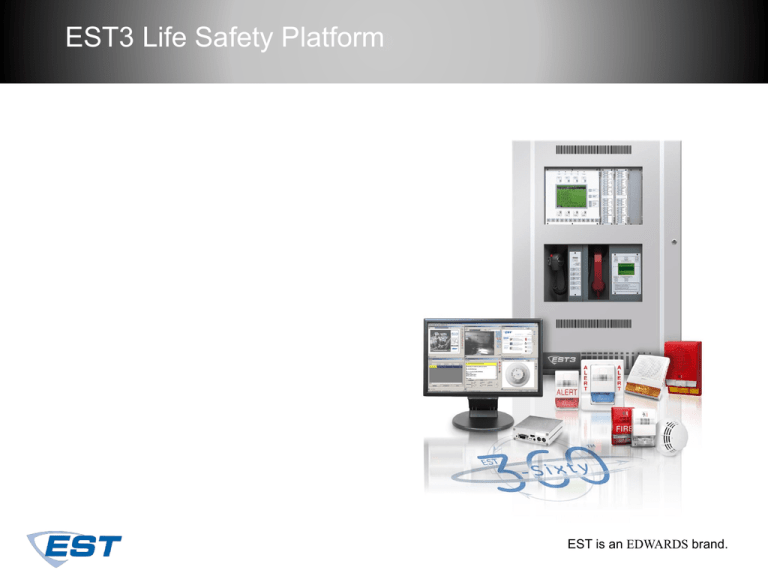
EST3 Life Safety Platform EST is an EDWARDS brand. What is EST3 Emergency Communication Network Platform for: ▪ Advanced Life Safety System ▪ Emergency Evacuation ▪ Security ▪ Fireworks Graphical Interface ▪ CCTV What is EST3 Life Safety Emergency Communication Smoke and Fire Detection Sprinkler System Supervision EST3 - Life Safety Platform Signature Devices EST3 EST3 Event Printer FireWorks EST3 Global Market Objectives International Standards Multilingual Modular Construction Site Configurable Fundamental Software Control EST3 General Features Retrofit and New Construction Standalone or Network Conventional or Analog Bells, Horns, Speakers, Strobes Survivability EST3 Technical Advances Lower Installation Costs Lower Owner Operating Costs Multi-Function Platform Multi-Priority Token Network Improved Response Times Improved Emergency Communications Signature Series Devices Windows Based System Programming Some New Terms Node… A panel or cabinet /w CPU LRM... Local Rail Module CDM... Control Display Modules EST3 Applications In a word... flexible Serve medium to large multiple building systems Small systems Standalone systems Single network systems Multi-function network Multiple network systems EST3 Node Architecture CPU LCD LCD CPU EST3 Node Architecture CPU LCD Local Rail Local Rail EST3 Node Architecture CPU LCD Local Rail LRM CDM LRM CDM LRM Up to 19 LRMs LRM Control Display Module Local Rail Module EST3 Node Architecture CPU LCD Stand Alone System Capacities Node 1 Local Rail LRM LRM CDM CDM ▪ 19 Local Rail Modules +CPU ▪ 5 SIGA Data Controllers 2 Loops per Controller 2 x 5 x 250 =2500 points ▪ 4 Power Supplies 4 x 7A = 28A LRM Up to 19 LRMs LRM ▪ 15 IDC8/4 Modules 15 x 8 =120 zones EST3 Network Architecture 64 x 2500 =160,000 points 64 x 28 = 1792 A 64 x 120 =7680 circuits Up to 64 Nodes Multiple Node Network Peer to peer network using multi-priority token 2 Fibers 2 Wires Alarm response independent of node count Alarm response less than 3 seconds Nodes Class ‘B’ Multiple Node Network 5000’ between any three nodes RS485 Data Communications 2 Fibers 2 Wires 38.4 Kbaud Class ‘B’ two wire, Class ‘A’ close ring Re-transmission and isolation between nodes Short Haul Modem, 5 miles Nodes Class ‘A’ Single Building Audio Audio Data High speed audio data is RS485 Class ‘B’ or ‘A’ Can use Fiber 2 wire pair carries 8 audio channels Network Data Analog phone riser to SIG modules, Class ‘B’ or ‘A’ Fire Phone Riser Single Building Network Network Data ▪ Twisted Pair ▪ 5000’ between 3 nodes Audio Data Network Data Audio Data ▪ Twisted Pair ▪ 5000’ between 3 nodes ▪ 8 Channel Audio Analog Fire Phone Fire Phone Riser ▪ Twisted Shielded ▪ 4000’ ▪ Master Phone Line Riser to SIGA-CC1s Multiple Building Network Multiple Control Panels Location Message Routing Overlapping Zone Controls EST3 Fire Functionality Via Signature Data Circuit ▪ Intelligent Smoke, Heat & CO Detection Very Intelligent ▪ Manual Pull Stations, 1 & 2 Stage ▪ N.O. Alarm Latching, Class ‘B’ or ‘A’ For Alarm Contact Devices ▪ N.O. Delayed Latching, Class ‘B’ or ‘A’ For Waterflow /w electronic time delay ▪ N.O. Active Latching, Class ‘B’ or ‘A’ For Sprinkler Supervisory Contact Devices EST3 Fire Functionality Via Signature Data Circuit ▪ N.O. Active Non-latching, Class ‘B’ or ‘A’ For Monitor Contacts such as air flow or damper position ▪ Two-Wire Smoke, Verified Y/N, ‘B’ or ‘A” For Conventional two-wire smoke detectors ▪ NAC, Audible, Visual or Auxiliary, Class ‘B’ or ‘A’ For polarized notification devices ▪ Auxiliary Control Relays, Form ‘C’ For Fan, Damper, Elevator control ▪ Telephone Circuits /w Busy Signal EST3 Fire Functionality Conventional Hardwire Circuits ▪ Class ‘B’ Alarm, Supervisory, Monitor Inputs ▪ Latching or Non-latching by circuit ▪ Verified or Non-verified by circuit ▪ European Operation, short as trouble ▪ NAC, Audible, Visual, or Auxiliary Class ‘B’ Zoned Audio Circuits ▪ Class ‘B’ or ‘A’ ▪ Allows delivery of multiple simultaneous messages EST3 Fire Functionality Control Panel ▪ 8 x 21 Backlit LCD w/ FA Common Controls ▪ optional conventional LED/switch control / display ▪ audio source unit & fire fighter’s telephone Programs & Tools Programs ▪ Each node contains firmware which is essentially an operating system ▪ Project specific (data files) upload from a PC to system nodes System Definition Utility [SDU] ▪ Creates project specific software System Definition Utility Windows®-based Virtually any-point-to-any-point System management Market place Forms Common [alarm, supervisory, monitor] Zoning and multi-stage Labels and Rules Label ▪ Message “Floor 3” ▪ Label ‘4L_Alarm_Floor_3’ Rule ALARM ‘4L_Alarm_Floor_3’ : ON ‘4L_NAC_Floor_3’ ; Messages & Labels Input Zone Labels Location Messages Output Zone Labels 7L_Alarm_Floor_6 Floor 6 7L_Nac_Floor_6 6L_Alarm_Floor_5 Floor 5 6L_Nac_Floor_5 5L_Alarm_Floor_4 Floor 4 5L_Nac_Floor_4 4L_Alarm_Floor_3 Floor 3 4L_Nac_Floor_3 3L_Alarm_Floor_2 Floor 2 3L_Nac_Floor_2 2L_Alarm_Floor_Gnd Ground Floor 2L_Nac_Floor_Gnd 1L_Alarm_Floor_Base Basement 1L_Nac_Floor_Base Evac Rule - fire, above, below for 3rd Floor [ALARM3] ALARM ‘4L_Alarm_Floor_3’ : ON ‘5L_NAC_Floor_4’, ON ‘4L_NAC_Floor_3’, ON ‘3L_NAC_Floor_2’; Evac Rule Above, Fire, Below for Entire Building [TOWER_ALARM] ALARM ‘(n:1-7)L_Alarm_Floor_*’ : ON ‘(n+1)L_NAC_Floor_*’, ON ‘(n)L_NAC_Floor_*’, ON ‘(n-1)L_NAC_Floor_*’; Four Step Process Define project parameters Configure cabinets, network routing, LRMs, devices & communication ports Define Objects such as Logical Zone, And, Matrix Groups, time controls Use Rules to establish relationships EST3 Life Safety Platform EST3 Off Premise Communications 3-MODCOM Modem Communicator EST3 SIGA-IPHS SIGA-IPHS Adding Security Graphics Printer Event Printer FireWorks 3-SAC 3MODCOM Phone Lines KPDISP -CF KPDISP Keypad Display SIGA-SEC2 SIGA2PS SIGAMD SIGA2PS Thank You!


