International Research Journal of Engineering and Technology (IRJET)
e-ISSN: 2395-0056
Volume: 08 Issue: 02 | Feb 2021
p-ISSN: 2395-0072
www.irjet.net
DESIGN OF PRESSURE VESSEL SADDLE AND ZICK ANALYSIS
Mr. Meet Parmar1, Dr. Dhaval Shah2, Mr. Manish Sonar3
1Graduate student, Dept. of Mechanical Engineering, Institute of Technology, Nirma University, Gujarat, India
2Assistant Professor, Dept. of Mechanical Engineering, Institute of Technology, Nirma University, Gujarat, India
3Assistant Manager (RPV Eng.), Larsen and Toubro Limited, Gujarat India
---------------------------------------------------------------------***---------------------------------------------------------------------
Abstract - Supports are the important part of a pressure
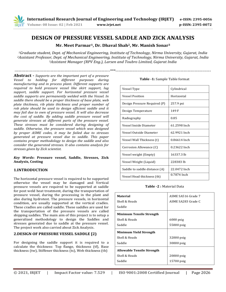
Table -1: Sample Table format
Vessel to holding for different purposes during
manufacturing and in process plant. Different supports are
required to hold pressure vessel like skirt support, lug
support, saddle support. For horizontal pressure vessel
saddle supports are permanently welded with the Vessel. In
saddle there should be a proper thickness of base plate, web
plate thickness, rib plate thickness and proper number of
rob plate should be used to design efficient saddle and it
may fail due to own of pressure vessel. It will also decrease
the cost of saddle. By adding saddle pressure vessel will
generate stresses at different parts of the pressure vessel.
These stresses must be considered during designing of
saddle. Otherwise, the pressure vessel which was designed
by proper ASME codes, it may be failed due to stresses
generated at pressure vessel due to saddle. This paper
contains proper methodology to design the saddle and also
consider the generated stresses. It also contains analysis for
stresses given by Zick scientist.
Key Words: Pressure vessel, Saddle, Stresses, Zick
Analysis, Costing
1.INTRODUCTION
Vessel Type
Cylindrical
Vessel Position
Horizontal
Design Pressure Required (P)
257.9 psi
Design Temperature
149 F
Radiography
0.85
Vessel Inside Diameter
61.2598 Inch
Vessel Outside Diameter
62.9921 Inch
Vessel Wall Thickness (t)
0.86614 Inch
Corrosion Allowance (C)
0.23622 Inch
Vessel weight (Empty)
16337.3 lb
Vessel Weight (Liquid)
228383 lb
Saddle to saddle distance (A)
22.0472 Inch
Vessel Head thickness (th)
The horizontal pressure vessel is required to be supported
otherwise the vessel may be damaged and Vertical
pressure vessels are required to be supported at saddle
for post weld heat treatment, during the transportation of
pressure vessel, during the processing in the plant and
also during hydrotest. The pressure vessels, in horizontal
condition, are usually supported at the vertical cradles.
These cradles are called saddle. These saddles are used for
the transportation of the pressure vessels are called
shipping saddles. The main aim of this project is to setup a
generalized methodology to design the Saddles and
stresses generated due to saddle at the pressure vessel.
The project work also carried about Zick Analysis.
0.7874 Inch
Table -2 : Material Data
Material
ASME SA516 Grade 7
Shell & Heads
ASME SA283 Grade C
Saddle
Minimum Tensile Strength
Shell & Heads
6000 psig
Saddle
55000 psig
2.DESIGN OF PRESSURE VESSEL SADDLE [2)
Minimum Yield Strength
Shell & Heads
32000 psig
For designing the saddle support it is required to a
calculate the thickness: Top flange, thickness (tf), Base
thickness (tw), Stiffener thickness (ts), Web thickness (tb)
Saddle
30000 psig
© 2021, IRJET
|
Impact Factor value: 7.529
Allowable Tensile Strength
|
Shell & Heads
20000 psig
Saddle
15700 psig
ISO 9001:2008 Certified Journal
|
Page 2026
International Research Journal of Engineering and Technology (IRJET)
e-ISSN: 2395-0056
Volume: 08 Issue: 02 | Feb 2021
p-ISSN: 2395-0072
www.irjet.net
Vessel Layout
Fig -2: I Section view of Saddle
2.1 Determination of top flange thickness (tf)
Fig -1: Pressure Vessel Layout
√(
Distance from tangent line to Saddle support can be found
from the trial and error method.
*
Head wall thickness(min.) (th) = 0.7874 Inch
Saddle support to tangent line distance (A) = 22.0472 Inch
Tangent line to head depth distance,
= 16.102 Inch
[
–
]
[
]
External depth of Head,
Total vessel overall length,
√
√
189.764 + (2 * 16.1024)
2.2 Determination of web plate thickness (tw)
© 2021, IRJET
|
Impact Factor value: 7.529
|
ISO 9001:2008 Certified Journal
|
Page 2027
International Research Journal of Engineering and Technology (IRJET)
e-ISSN: 2395-0056
Volume: 08 Issue: 02 | Feb 2021
p-ISSN: 2395-0072
www.irjet.net
= 0.88 * 62.9921
*
( ) +
From Equation (4.4),
√(
*
= 3.09974
√
{
}
The distance between two stiffeners is,
Rib plate width,
[
[
]
]
[
[
]
]
Width of outside stiffeners
2.3 Calculation of base plate thickness (tb)
√*
+
√*
+
Fig -3: Designed saddle 2D Drawing
2.4 Determination thickness of stiffeners ( )
3 ANALYSIS OF PRESSURE VESSEL SADDLE [1]
An approximate number for stiffeners is:
Stresses at Pressure Vessel by attaching two number of
saddles,
3.1 Longitudinal Stresses [3]
© 2021, IRJET
|
Impact Factor value: 7.529
|
ISO 9001:2008 Certified Journal
|
Page 2028
International Research Journal of Engineering and Technology (IRJET)
e-ISSN: 2395-0056
Volume: 08 Issue: 02 | Feb 2021
p-ISSN: 2395-0072
Longitudinal force = 5.32 *
www.irjet.net
lb
(
,
(
(
)
)
*
= 8.96382 Inch
= 227.6811 mm < 300 mm
3.2 Transverse Direction Stresses [3]
Fig -4: FBD for stresses in longitudinal direction
[
[
]
]
Fig -5: FBD for stresses in transverse direction
[
© 2021, IRJET
|
Impact Factor value: 7.529
|
]
ISO 9001:2008 Certified Journal
|
Page 2029
International Research Journal of Engineering and Technology (IRJET)
e-ISSN: 2395-0056
Volume: 08 Issue: 02 | Feb 2021
p-ISSN: 2395-0072
[
www.irjet.net
]
[
3.4 Bending stress and bending moment at midspan of Pressure Vessel [1]
(
+
(
,
3.3 Calculation of Bending Moment and Bending
stress at saddles [1]
Bending moment in saddle (compression and tension)
(
(
)
3.5 Shell Stresses cause because of Internal
(
© 2021, IRJET
Pressure [1]
)
|
Impact Factor value: 7.529
|
ISO 9001:2008 Certified Journal
|
Page 2030
International Research Journal of Engineering and Technology (IRJET)
e-ISSN: 2395-0056
Volume: 08 Issue: 02 | Feb 2021
p-ISSN: 2395-0072
www.irjet.net
3.6 Tangential shear stress [1]
(
)
Tangential shear stress at shell (S2)
(
(
)
)
(
)
Ratio of the stress acting is lesser than 1.
So, the Tangential Stress is safe for design.
Tangential shear stress at shell,
Ratio of the stress acting is lesser than 1. So the Tangential
Stress is safe for design.
Tangential shear stress at shell (S2),
(
)
Ratio of the stress acting is lesser than 1.
(
)
So, the Tangential Stress is safe for design.
Tangential shear stress at head, Where
Ratio of the stress acting is lesser than 1. So the Tangential
Stress is safe for design.
Ratio of the stress acting is lesser than 1. So, the
Tangential Stress is safe for design.
Tangential shear stress at head (Sh), Where of A > R/2
and ring isn’t used
Additional tangential shear stress at head
© 2021, IRJET
|
Impact Factor value: 7.529
|
ISO 9001:2008 Certified Journal
|
Page 2031
International Research Journal of Engineering and Technology (IRJET)
e-ISSN: 2395-0056
Volume: 08 Issue: 02 | Feb 2021
p-ISSN: 2395-0072
www.irjet.net
In case of A
(
*
(
*
Ratio of the stress acting is lesser than 1. So the
Ratio of the stress acting is lesser than 1. So the Tangential
Circumferential Stress is safe for design.
Stress is safe for design.
Circumferential stress at bottom part of shell,
3.7 Circumferential stress [1]
(
*
Circumferential stress at saddle horn
Where
and unstiffened
(
*
(
*
Ratio of the stress acting is lesser than 1. So the
Circumferential Stress is safe for design
3.8 Check of tension at Web of the saddle [1]
Horizontal force at web,
Effective web area,
Ratio of the stress acting is lesser than 1. So the
Circumferential Stress is safe for design.
Stress in web,
Circumferential stress calculation at horn of saddle,
Stress which is allowable at web, as below
Where L < 8 R and unstiffened
(
© 2021, IRJET
*
|
Impact Factor value: 7.529
|
ISO 9001:2008 Certified Journal
|
Page 2032
International Research Journal of Engineering and Technology (IRJET)
e-ISSN: 2395-0056
Volume: 08 Issue: 02 | Feb 2021
p-ISSN: 2395-0072
www.irjet.net
3.10 Bearing Pressure [1]
Vertical force at web,
Stress in web,
Stress which is allowable in web (compression),
Which is lesser than 750 (Allowable)
4. CONCLUSIONS
As per calculation of different for saddle parts and stress
calculated from Zick method and the comparison between
stresses for different locations are lesser than the Stress
which is allowable. So, the design of Pressure Vessel
Saddle is safe for manufacturing. Stresses generated at
pressure vessel due to attached saddle are lesser than the
Stress which is allowable.
3.9 Check the lowest section of Saddle [1]
REFERENCES
Zick, LP Stresses in large horizontal cylindrical
pressure vessels on two saddle supports. In: 1985
ASME (eds). Pressure vessel and piping: design and
analysis – a decade of progress 1985; vol. 2 New
York: ASME, pp. 959–970.
[2] Ong, L. S., & Lu, G., Optimal Support Radius of LooseFitting Saddle Support, International Journal of
Pressure Vessel & Piping, 54(1993) 465-79
[3] Richard Budynas, J. Nisbett, Shigley's Mechanical
Engineering Design, 8th ed., New York:McGrawHill, ISBN 978-0-07-312193-2page 108
[1]
Fig -6: Saddle at lowest section
The lowest section of the saddle is as shown in figure 6
For resisting this force, the area of required in web plate
required is,
( )
(
)
The calculated stress,
The Stress which is allowable,
So, for horizontal force (F) the thickness of the web plate is
satisfied.
© 2021, IRJET
|
Impact Factor value: 7.529
|
ISO 9001:2008 Certified Journal
|
Page 2033


