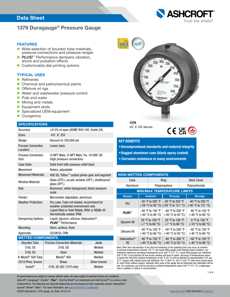
Data Sheet 1379 Duragauge® Pressure Gauge TM FEATURES Wide selection of bourdon tube materials, pressure connections and pressure ranges PLUS!™ Performance dampens vibration, shock and pulsation effects Customizable dial printing options TYPICAL USES Refineries Chemical and petrochemical plants Offshore oil rigs Water and wastewater pressure control Pulp and water Mining and metals Equipment skids Specialized OEM equipment Cryogenics 1379 SPECIFICATIONS Accuracy: ±0.5% of span (ASME B40.100, Grade 2A) Sizes: 41⁄2˝, 6˝, 81⁄2˝ Range: Vacuum to 100,000 psi Process Connection Location: Lower, back Process Connection Size: 1 Case Style: Solid front with pressure relief back Movement: Movement Materials: Rotary, adjustable Window Material: Dial: Pointer: Weather Protection: Dampening Options: Mounting: KEY BENEFITS • Uncompromised standards and material integrity ⁄4 NPT Male, 1⁄2 NPT Male, 9⁄16 -18 UNF-2B (high pressure connection) 400 SS, Teflon™ coated pinion gear and segment Glass (STD.), acrylic window (OPT.), shatterproof glass (OPT.) Aluminum, white background, black pressure scale Micrometer adjustable, aluminum Dry case: Case not sealed, recommend for weather protected environment only Liquid filled or field fillable: IP66 or NEMA 4X Hermetically sealed: IP66 Liquid: glycerin, silicone, Halocarbon®, PLUS! ™ Performance Stem, surface, flush Approvals: CE/UKCA, CRN WETTED COMPONENTS Bourdon Tube Process Connection Materials 316L SS 316L SS 316L SS Steel K-Monel® 500 Tube Monel® 400 C510 Phos. bronze Brass Iconel® 316L SS (60-1379 only) 41⁄2˝, 6˝, 81⁄2˝ dial size Joints Welded Welded Welded Silver brazed Welded • Rugged aluminum case (black epoxy coated) • Corrosion resistance in many environments NON-WETTED COMPONENTS Case Ring Back Cover Aluminum Polypropylene Polycarbonate MIN/MAX TEMPERATURE LIMITS Version Dry Ambient Process Storage -20 °F to 200 °F -20 °F to 250 °F -40 °F to 250 °F (-29 °C to 93 °C) (-29 °C to 121 °C) (-40 °C to 121 °C) PLUS! ™ -40 °F to 150 °F -40 °F to 200 °F (-40 °C to 66 °C) (-40 °C to 93 °C) -40 °F to 150 °F (-40 °C to 66 °C) Glycerin fill 20 °F to 150 °F (-7 °C to 66 °C) 20 °F to 150 °F (-7 °C to 66 °C) 0 °F to 150 °F (-18 °C to 66 °C) Silicone fill -40 °F to 150 °F -40 °F to 200 °F (-40 °C to 66 °C) (-40 °C to 93 °C) -40 °F to 150 °F (-40 °C to 66 °C) Halocarbon® fill -40 °F to 150 °F -40 °F to 200 °F (-40 °C to 66 °C) (-40 °C to 93 °C) -40 °F to 150 °F (-40 °C to 66 °C) Note: Other than discoloration of the dial and hardening of the gasketing that may occur as ambient or process temperatures exceeds 150 °F, non-liquid-filled gauges with standard glass windows, can withstand continuous operating temperatures up to 250 °F (121 °C). Liquid-filled gauges can withstand 200 °F (93 °C) but glycerin fill and acrylic window will tend to yellow. Accuracy at temperatures above or below the reference ambient temperature of 68 °F (20 °C) will be affected by approximately 0.4% per 25°F. Gauges with welded joints will withstand 750 °F (400 °C), 450 °F (232 °C) with silver brazed joints for short times without rupture, although other parts of the gauge will be destroyed and calibration will be lost. For continuous use and for process or ambient temperatures above 250 °F (121 °C), a diaphragm seal or capillary or siphon is recommended. 1 of 4 All specifications are subject to change without notice. All sales subject to standard terms and conditions. Ashcroft®, Duragauge®, DuraVis™, Plus!™, Trust the Shield® are trademarks and Gold ServiceSM is a service mark of Ashcroft Inc. The following non-Ashcroft trademarks are the property of their respective owners: Halocarbon®, Inconel®, Monel®, Teflon™. For more information, see Ashcroft Brands & Trademarks ©2023 Ashcroft Inc. 1379_gauge_ds_RevK_04-03-23 ashcroft.com | 1.800.328.8258 | Contact Us Data Sheet 1379 Duragauge® Pressure Gauge ORDERING CODE Example: 451379 S Dial Size/Model Code 451379 - 41⁄2˝ aluminum case, solid front 451379 601379 - 6˝ aluminum case, solid front 851379 - 81⁄2˝ aluminum case, solid front System (tube and process connection) A - Bronze tube, brass process connection, max. pressure connection 1,000 psi P - K-Monel® 500 tube, Monel® 400 process connection, max. pressure 30,000 psi R - 316L SS tube, steel process connection, max. pressure 20,000 psi S - 316 SS tube, 316L SS process connection, max. pressure 20,000 psi S W W - Inconel® 718 tube, Inconel 718 process connection (50,000 to 100,00 psi ranges) Case Design S - Solid front case, dry SH - Solid front case, dry, sealed, hermetically sealed (n/a 8 ½˝ size) SL - Solid front case, liquid filled (glycerin std., n/a 8 ½˝ size) Process Connection Sizes 02 - 1⁄4 NPT Male, N/A for ranges over 20,000 psi 04 - 1⁄2 NPT Male, N/A for ranges over 20,000 psi 09 - 9⁄16 18 UNF-2B, high pressure fitting, standard for pressures over 20,000 psi Process Connection Location L - Lower B - Back D - Side (3 o’clock) E - Side connection (9 o’clock) T - Top connection Options (If choosing an option(s) must include a “X”) (See table 1 on page 3 for more options) LL - PLUS!™ Performance ND - PLUS!™ Performance, silicone free (glycerin and silicone filled gauges) NZ - PLUS!™ Performance silicone free (dry gauge) GV - Silicone case fill GX - Halocarbon® case fill 6B - Cleaned for gaseous oxygen service NH - Stainless steel tag wired to case SH 04 L XLL 15# SH 04 L X__ LL 5G - Attach one accessory to gauge. Applicable to PL02 pressure limiting valve, V01,V02,V03 valves, 1098, 1100, 1198, 2198 siphons, 7001, 7004 needle valves, 1115 capillary, 1106 pulsation dampner, 1112, PD02 pressure snubbers, MDV swivel adapter, 2265 electric warning contact Range (coding examples only, see range table on page 3 for all standard ranges) Single Scales 15# - 15 psi 1BR - 1 bar 1KSC - 1 kilograms per sq. cm 100KP - 100 kilopascal Dual Scales 15#/BR - 15 psi inner scale, 1 bar outer scale 1BR/# - 1 bar inner scale, 15 psi outer scale 15# When selecting a diaphragm seal or isolation ring, refer to the Min/Max Guide for compatibility with this gauge or scan the QR code to the right. 2 of 4 All specifications are subject to change without notice. All sales subject to standard terms and conditions. Ashcroft®, Duragauge®, DuraVis™, Plus!™, Trust the Shield® are trademarks and Gold ServiceSM is a service mark of Ashcroft Inc. The following non-Ashcroft trademarks are the property of their respective owners: Halocarbon®, Inconel®, Monel®, Teflon™. For more information, see Ashcroft Brands & Trademarks ©2023 Ashcroft Inc. 1379_gauge_ds_RevK_04-03-23 ashcroft.com | 1.800.328.8258 | Contact Us Data Sheet 1379 Duragauge® Pressure Gauge TABLE 1 (Odering Codes Continued) Gauges calibrated to compensate for absolute pressure DA Dial marking (text marking on the dial) EP Maximum pointer (adjustable, N/A with liquid filled or hermetically sealed cases) HY Hydrostatic/pneumatic testing (system pressurized to 150% of rated system pressure for 5 minutes. Overload stop STD.) NG Non-glare glass (N/A with liquid fill or hermetically sealed cases) OS Overload stop PD Acrylic window (STD. with liquid filled or hermetically sealed cases) SH Red set hand, stationary SG Safety glass TS Throttle screw (STD. with liquid filled, hermetically sealed or PLUS!™ Performance) VS Underload stop C4 Traceable calibration certificate 56 Flush mounting ring BF Surface mounting bracket D3 DuraVis™ retroreflective dial (41/2˝ and dry case only) TM 2˝ pipe mounting bracket (4½˝ dial size only) Vacuum AB STANDARD PRESSURE RANGES Compound OPTION Positive Pressure CODE psi 30IMV – V/15# – V/30# – V/60# – V/100# – 15# 20# – 30# – 60# – 100# 120# – 160# 200# – 300# – 400# 500# 600# 800# – 1000# 1500# 2000# – 3000# – 4000# 5000# 6000# 8000# – 10000# 15000# 20000# 30000# 50000# 80000# 100000# bar N1BR N1/0.6BR – N1/1.5BR – N1/3BR – N1/5BR – N1/9BR 1BR – 1.6BR – 2.5BR 4BR 6BR – – 10BR – – 16BR – 25BR – – 40BR – 60BR – 100BR – 160BR – 250BR – – 400BR – 600BR – 1000BR 1600BR 2500BR 4000BR 6000BR - kPa N100KP N100/60KP – N100/150KP – N100/300KP – N100/500KP – N100/900KP 100KP – 160KP – 250KP 400KP 600KP – – 1000KP – – 1600KP – 2500KP – – 4000KP – 6000KP – 10000KP – 16000KP – 25000KP – – 40000KP – 60000KP – 100000KP - mPa N1MP 0.1/0.06MP – N0.1/0.15MP – N0.1/0.3MP – N0.1/.5MP – N0.1/.9MP 0.1MP – 0.16MP – 0.25MP 0.4MP 0.6MP – – 1MP – – 1.6MP – 2.5MP – – 4MP – 6MP – 10MP – 16MP – 25MP – – 40MP – 60MP – 100MP 160MP 250MP 400MP 600MP - kg/cm2 N1KG N1/0.6KG – N1/1.5KG – N1/3KG – N1/5KG – N1/9KG 1KG – 1.6KG – 2.5KG 4KG 6KG – – 10KG – – 16KG – 25KG – – 40KG – 60KG – 100KG – 160KG – 250KG – – 400KG – 600KG – 1000KG 1600KG 2500KG 4000KG 6000KG - 3 of 4 All specifications are subject to change without notice. All sales subject to standard terms and conditions. Ashcroft®, Duragauge®, DuraVis™, Plus!™, Trust the Shield® are trademarks and Gold ServiceSM is a service mark of Ashcroft Inc. The following non-Ashcroft trademarks are the property of their respective owners: Halocarbon®, Inconel®, Monel®, Teflon™. For more information, see Ashcroft Brands & Trademarks ©2023 Ashcroft Inc. 1379_gauge_ds_RevK_04-03-23 ashcroft.com | 1.800.328.8258 | Contact Us Data Sheet 1379 Duragauge® Pressure Gauge DIMENSIONS in [ ] are millimeters For reference only, consult Ashcroft for specific dimensional drawings Dial Size A B C 41⁄2 513⁄16 [148] 33⁄8 [86] 6 79⁄16 [192] 81⁄2 101⁄16 [256] Inches D E F G H J 47⁄8 [124] 15⁄8 [41] 53⁄8 [137] 11⁄2 [42] 315⁄16 [100] 7 ⁄8 [20] 11⁄16 [27] 0.218 1⁄8 - 1⁄2 [6] [3] [13] 31⁄2 [89] 65⁄8 [162] 15⁄8 [41] 7 [178] 11⁄2 [42] 41⁄2 [114] 7 ⁄8 [20] 11⁄16 [27] 0.218 1⁄8 - 1⁄2 [6] [3] [13] 27⁄8 [73] 43⁄4 #10-24 [121] 11⁄16 [27] 95⁄8 [244] 15⁄8 [41] 6 [152] 13⁄8 [35] AA CC A A A BB CC B B B JJ J J C C C K L LL 11⁄16 [27] M N N N WW W AA A A A HH H H H V Weight (lbs) 21⁄8 [54] 5 ⁄8 [16] 25⁄8 [67] 2.5 (Dry) 3.5 (L.F.) 21⁄8 [54] 5 ⁄8 [16] 25⁄8 [67] 3.0 (Dry) 4.0 (L.F.) S 11 ⁄16 [17] not supplied notnot supplied supplied not not supplied by by supplied by by by Ashcroft Ashcroft Ashcroft Ashcroft Ashcroft TT FF F F F VV V V V TT 3- L3-dia. L dia. holes 3- L holes 3dia. L dia. holes 3- Lholes dia. holes on on E dia. E on dia. Bolt on EBolt dia. Circle ECircle on dia. Bolt EBolt Circle dia.Circle Bolt Circle GG G G G T T T 41⁄2˝ & 6˝ Lower Conn. TT T T T DD D D D 41⁄2˝ & 6˝ Back Conn. G G G HH H H H P P P 81⁄2˝ Lower Conn. DD threaded threaded threaded equally threaded equally threaded spaced equally spaced equally spaced equally spaced spaced K E dia. KBolt on on E dia. on Eon Bolt dia. Circle E on Circle dia. Bolt Circle Circle EBolt dia. Bolt Circle D DK KD K LLLL LLLL LL 81⁄2˝ Wall Conn. “C” WASHER SPACER POST (3 REQ’D) 81⁄2˝ Back Conn. “B” (3 REQ’D) HOLE IN PANEL (REAR VIEW) 41⁄2 6 [152] 55⁄8 [148] #10-24 x 15⁄8 7 6 73⁄4 [197] 73⁄10 [185] #1⁄4 -20 x 1 17 ⁄16 x 17∕64 x 5⁄8 1 ⁄94 x 1⁄2 x 1⁄16 113⁄32 RING O.D. "B" "C" Size of 3 Size of Spacer Screws Washers PANEL CUTOUT “A” DIA. 1/64 Inches Ring "A" O.D DIA. PP MOUNTING RING Used to flush mount gauge case. Standard finish in black; optional polished stainless steel finish is available. T T T C C C TC C T T MM M M M in Hole in in F F Hole FHole Fin inHole F Hole panel panel panel panelpanel 3 Mounting 3 Mounting 3 Mounting 3 studs Mounting studs 3 CC Mounting studs CCstuds CCstuds CC CC PANEL Type 1278M Series Flush Mounting Ring Gauge Size GG TT 4.5 (Dry) S S Nuts S &Swashers SNuts Nuts & washers Nuts & Nuts washers & washers & washers J W T P 1 ⁄8 - 1⁄2 9 3.19 [3] [13] [228] [80.9] B B B NN BB N SHOWING USE OF LEVEL TO LINE UP SPACER POSTS CASE 4 of 4 All specifications are subject to change without notice. All sales subject to standard terms and conditions. Ashcroft®, Duragauge®, DuraVis™, Plus!™, Trust the Shield® are trademarks and Gold ServiceSM is a service mark of Ashcroft Inc. The following non-Ashcroft trademarks are the property of their respective owners: Halocarbon®, Inconel®, Monel®, Teflon™. For more information, see Ashcroft Brands & Trademarks ©2023 Ashcroft Inc. 1379_gauge_ds_RevK_04-03-23 ashcroft.com | 1.800.328.8258 | Contact Us
