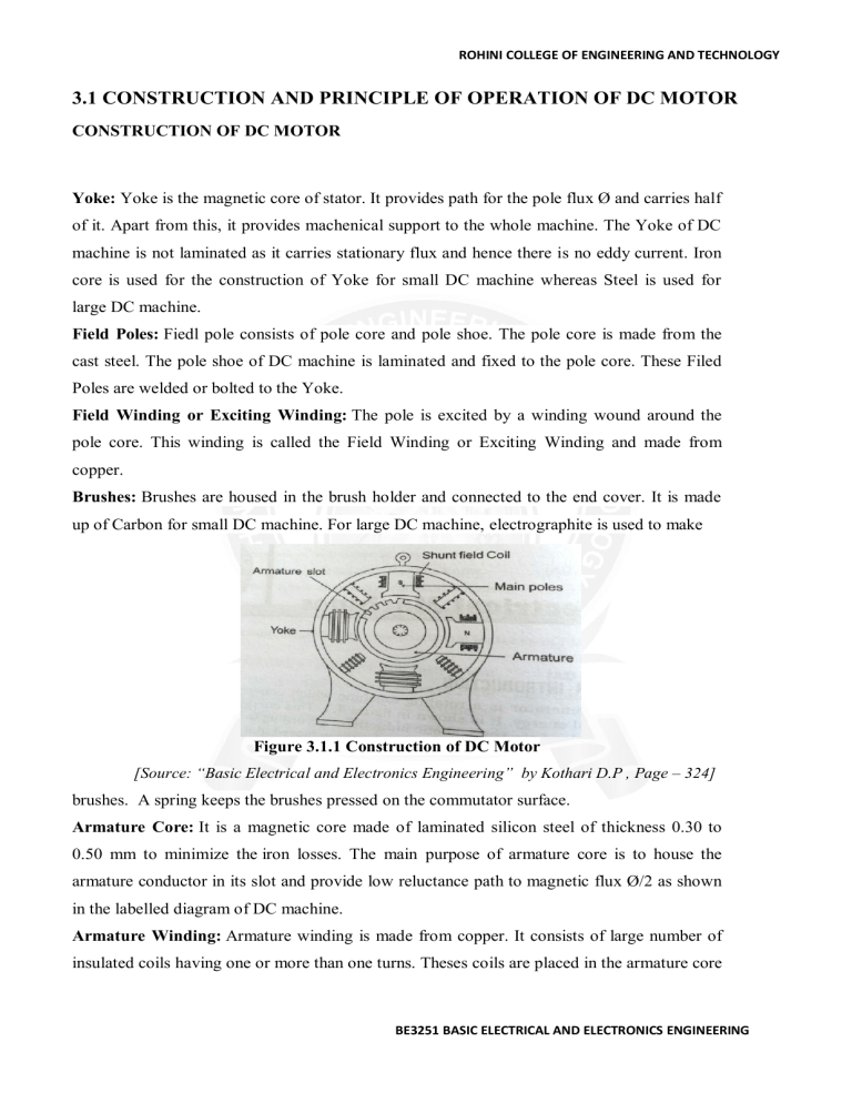
ROHINI COLLEGE OF ENGINEERING AND TECHNOLOGY 3.1 CONSTRUCTION AND PRINCIPLE OF OPERATION OF DC MOTOR CONSTRUCTION OF DC MOTOR Yoke: Yoke is the magnetic core of stator. It provides path for the pole flux Ø and carries half of it. Apart from this, it provides machenical support to the whole machine. The Yoke of DC machine is not laminated as it carries stationary flux and hence there is no eddy current. Iron core is used for the construction of Yoke for small DC machine whereas Steel is used for large DC machine. Field Poles: Fiedl pole consists of pole core and pole shoe. The pole core is made from the cast steel. The pole shoe of DC machine is laminated and fixed to the pole core. These Filed Poles are welded or bolted to the Yoke. Field Winding or Exciting Winding: The pole is excited by a winding wound around the pole core. This winding is called the Field Winding or Exciting Winding and made from copper. Brushes: Brushes are housed in the brush holder and connected to the end cover. It is made up of Carbon for small DC machine. For large DC machine, electrographite is used to make Figure 3.1.1 Construction of DC Motor [Source: “Basic Electrical and Electronics Engineering” by Kothari D.P , Page – 324] brushes. A spring keeps the brushes pressed on the commutator surface. Armature Core: It is a magnetic core made of laminated silicon steel of thickness 0.30 to 0.50 mm to minimize the iron losses. The main purpose of armature core is to house the armature conductor in its slot and provide low reluctance path to magnetic flux Ø/2 as shown in the labelled diagram of DC machine. Armature Winding: Armature winding is made from copper. It consists of large number of insulated coils having one or more than one turns. Theses coils are placed in the armature core BE3251 BASIC ELECTRICAL AND ELECTRONICS ENGINEERING ROHINI COLLEGE OF ENGINEERING AND TECHNOLOGY slots and connected appropriately in series and parallel depending on the type of winding. There are basically two types of winding: Lap Winding and Wave Winding. Commutator: It is a cylindrical structure made up of wedge shaped segments of high conductivity hard drawn copper. Hard drawn copper is used to reduce wear and tear of commutator surface. The segments are insulated from each other by 0.8 mm thick mica sheet. Shaft: Shaft of DC Motor is coupled to the load to transfer mechanical power. For DC Generator, shaft is coupled to prime mover to convert mechanical input energy into electrical output. Armature core, bearing, commutator etc. are mounted on the Shaft. PRINCIPLE OF OPERATION: Figure 3.1.2 Principle of Operation [Source: “Basic Electrical and Electronics Engineering” by Kothari D.P , Page – 466] Basic principle is “whenever a current carrying conductor is placed in magnetic field, it experiences a force tending to move it”. Above the conductor-field is weakened, below-field is strengthened, conductor moves upwards. Force exerted upwards depends upon the intensity, the direction of the current is reversed. Now field below-less, field above-more, conductor moves downwards. F= BLI newtons B= magnetic field intensity in wb/m2. L= length of the conductor. Direction of motion-flemings left hand rule. Thumb, fore finger, middle finger – mutually perpendicular. Fore finger-direction of field, Middle finger-direction of current, Thumb-direction of motion of conductor. BE3251 BASIC ELECTRICAL AND ELECTRONICS ENGINEERING ROHINI COLLEGE OF ENGINEERING AND TECHNOLOGY BACK EMF: Machine is working as a motor-voltages are induced, called as back emf. Lenz’s law-direction of back emf opposes the supply voltage. Eb=Φzn/60 x P/A volts. Voltage equation =V=Eb + Ia Ra. Ia = V-Eb/Ra. Eb –armature speed and armature current. Motor speed is high-back emfE b is large, armature current is small. Motor speed is low-back emf is less, armature current is high. BE3251 BASIC ELECTRICAL AND ELECTRONICS ENGINEERING
