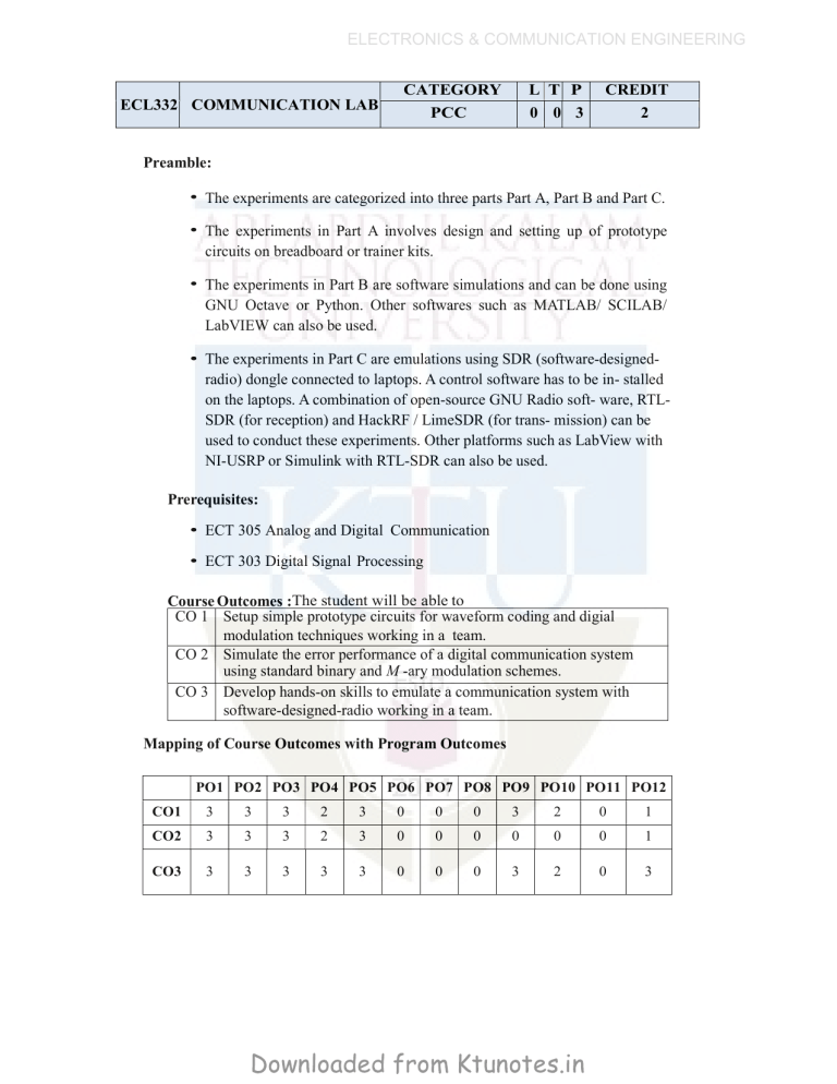
ELECTRONICS & COMMUNICATION ENGINEERING ECL332 COMMUNICATION LAB CATEGORY PCC L T P 0 0 3 CREDIT 2 Preamble: • The experiments are categorized into three parts Part A, Part B and Part C. • The experiments in Part A involves design and setting up of prototype circuits on breadboard or trainer kits. • The experiments in Part B are software simulations and can be done using GNU Octave or Python. Other softwares such as MATLAB/ SCILAB/ LabVIEW can also be used. • The experiments in Part C are emulations using SDR (software-designedradio) dongle connected to laptops. A control software has to be in- stalled on the laptops. A combination of open-source GNU Radio soft- ware, RTLSDR (for reception) and HackRF / LimeSDR (for trans- mission) can be used to conduct these experiments. Other platforms such as LabView with NI-USRP or Simulink with RTL-SDR can also be used. Prerequisites: • ECT 305 Analog and Digital Communication • ECT 303 Digital Signal Processing Course Outcomes :The student will be able to CO 1 Setup simple prototype circuits for waveform coding and digial modulation techniques working in a team. CO 2 Simulate the error performance of a digital communication system using standard binary and M -ary modulation schemes. CO 3 Develop hands-on skills to emulate a communication system with software-designed-radio working in a team. Mapping of Course Outcomes with Program Outcomes PO1 PO2 PO3 PO4 PO5 PO6 PO7 PO8 PO9 PO10 PO11 PO12 CO1 3 3 3 2 3 0 0 0 3 2 0 1 CO2 3 3 3 2 3 0 0 0 0 0 0 1 CO3 3 3 3 3 3 0 0 0 3 2 0 3 Downloaded from Ktunotes.in ELECTRONICS & COMMUNICATION ENGINEERING Assessment Pattern Mark Distribution; Total Mark 150 CIE 75 ESE 75 Continuous Internal Evaluation Pattern: Attribute Attendance Continuous assessment Internal Test (Immediately before the second series test) Mark 15 30 30 End Semester Examination Pattern: The following guidelines should be followed regarding award of marks. Attribute Preliminary work Implementing the work/Conducting the experiment Performance, result and inference (usage of equipments and trouble shooting) Viva voce Record Mark 15 10 25 20 5 General instructions: End-semester practical examination is to be conducted immediately after the second series test covering entire syllabus given below. Evaluation is to be conducted under the equal responsibility of both the internal and external examiners. The number of candidates evaluated per day should not exceed 20. Students shall be allowed for the examination only on submitting the duly certified record. The external examiner shall endorse the record. Experiments Part A Any two experiments are mandatory. The students shall design and setup simple prototype circuits with the help of available ICs. They can observe Waveforms produced by these circuits for standard ideal inputs. 1. FM generation and demodulation using PLL 2. Generation and Detection of PCM signals Downloaded from Ktunotes.in ELECTRONICS & COMMUNICATION ENGINEERING 3. Generation and Detection of Delta modulated signals 4. Generation and Detection of BPSK 5. Generation and Detection of 16-QPSK Part B All experiments are mandatory. The students shall write scripts to simulate components of communication systems. They shall plot various graphs that help to appreciate and compare performance. 1. Performance of Waveform Coding Using PCM 1. Generate a sinusoidal waveform with a DC offset so that it takes only positive amplitude value. 2. Sample and quantize the signal using an uniform quantizer with number of representation levels L. Vary L. Represent each value using decimal to binary encoder. 3. Compute the signal-to-noise ratio in dB. 4. Plot the SNR versus number of bits per symbol. Observe that the SNR increases linearly. 2. Pulse Shaping and Matched Filtering 1. Generate a string of message bits. 2. Use root rasied cosine pulse p(t) as the shapig pulse, and generate the corresponding baseband signal with a fixed bit duration Tb. You may use roll-off factor as α = 0.4. 3. Simulate transmission of baseband signal via an AWGN channel 4. Apply matched filter with frequency response Pr(f ) = P ∗(f ) to the received signal. 5. Sample the signal at mTb and compare it against the message sequence. 3. Eye Diagram 1. Generate a string of message bits. 2. Use rasied cosine pulse p(t) as the shapig pulse, and generate the corresponding baseband signal with a fixed bit duration Tb. You may use roll-off factor as α = 0.4. 3. Use various roll off factors and plot the eye diagram in each case for the received signal. Make a comparison study among them. Downloaded from Ktunotes.in ELECTRONICS & COMMUNICATION ENGINEERING 4. Error Performance of BPSK 1. Generate a string of message bits. 2. Encode using BPSK with energy per bit Eb and represent it using points in a signal-space. 3. Simulate transmission of the BPSK modulated signal via an AWGN channel with variance N0/2. 4. Detect using an ML decoder and plot the probability of error as a function of SNR per bit Eb/N0. 5. Error Performance of QPSK 1. Generate a string of message bits. 2. Encode using QPSK with energy per symbol Es and represent it using points in a signal-space. 3. Simulate transmission of the QPSK modulated signal via an AWGN channel with variance N0/2 in both I-channel and Q-channel. 4. Detect using an ML decoder and plot the probability of error as a function of SNR per bit Eb/N0 where Es = 2Eb. Part C Any two experiments are mandatory. The students shall emulate communication systems with the help of software-defined-radio hardware and necessary control software. Use available blocks in GNU Radio to implement all the signal processing. These experiments will help students to appreciate better how theoretical concepts are translated into practice. 1. Familiarization with Software Defined Radio (Hardware and Control Software) 1. Familiarize with an SDR hardware for reception and transmission of RF signal. 2. Familiarize how it can be interfaced with computer. 3. Familiarize with GNU Radio (or similar software’s like Simulink/ LabView) that can be used to process the signals received through the SDR hardware. 4. Familiarize available blocks in GNU Radio. Study how signals can be generated and spectrum (or power spectral density) of signals can be analyzed. Study how filtering can be performed. Downloaded from Ktunotes.in ELECTRONICS & COMMUNICATION ENGINEERING 2. FM Reception 1. Receive digitized FM signal (for the clearest channel in the lab) using the SDR board. 2. Set up an LPF and FM receiver using GNU Radio. 3. Use appropriate sink in GNU Radio to display the spectrum of signal. 4. Resample the voice to make it suitable for playing on computer speaker. 3. FM Transmission 1. Use a wave file source. 2. Set up an FM transmitter using GNU Radio. 3. Resample the voice source and transmit using the SDR. Schedule of Experiments Every experiment should be completed in three hours. Text books and References 1. Carl Laufer, “The Hobbyist’s Guide to the RTL-SDR: Really Cheap Software Defined Radio” 2. Neel Pandeya, “Implementation of a Simple FM Receiver in GNU Radio,” https://kb.ettus.com/ 3. WH Tranter, KS Shanmugan, TS Rappaport, KL Kosbar, “Principles of Communication Systems Simulation with Wireless Applications”, Prentice Hall 4. Michael Ossmann, “Software Defined Radio with HackRF,” YouTube Tutorial 5. Mathuranathan Viswanathan, “Digital Modulations using Python” Downloaded from Ktunotes.in


