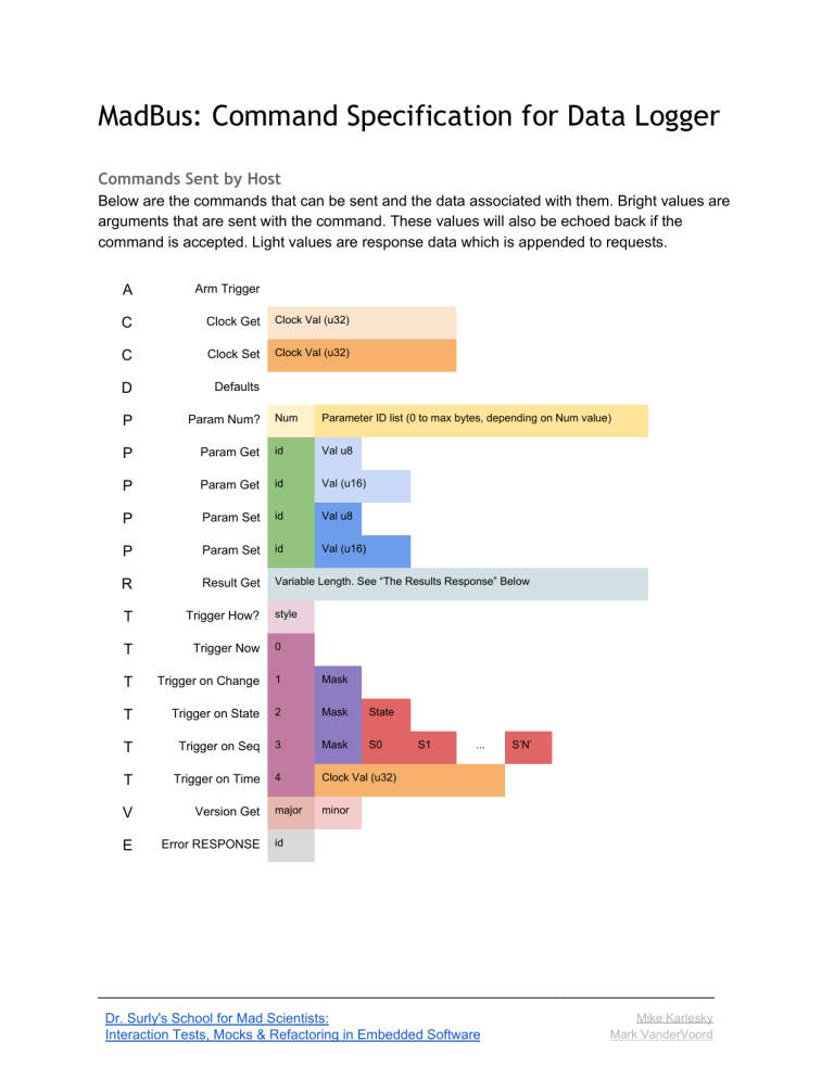
MadBus: Command Specification for Data Logger Commands Sent by Host Below are the commands that can be sent and the data associated with them. Bright values are arguments that are sent with the command. These values will also be echoed back if the command is accepted. Light values are response data which is appended to requests. A Arm Trigger C Clock Get Clock Val (u32) C Clock Set Clock Val (u32) D Defaults P Param Num? P Num Parameter ID list (0 to max bytes, depending on Num value) Param Get id Val u8 P Param Get id Val (u16) P Param Set id Val u8 P Param Set id Val (u16) R Result Get Variable Length. See “The Results Response” Below T Trigger How? T Trigger Now 0 T Trigger on Change 1 Mask T Trigger on State 2 Mask State T Trigger on Seq 3 Mask S0 T Trigger on Time 4 Clock Val (u32) V Version Get major minor E Error RESPONSE style S1 ... S’N’ id __________________________________________________________________________ Dr. Surly's School for Mad Scientists: Interaction Tests, Mocks & Refactoring in Embedded Software Mike Karlesky Mark VanderVoord The Framing The framing of our message protocol is the same as the one presented in the previous class, with one small change: an extended length field. As a reminder, here are the requirements again: ● ● ● ● ● ● ● The first byte of a packet is a left bracket [ The second byte of a packet is the command ID, an ASCII letter in uppercase The third byte of a packet is the length of the data, an ASCII number between 0 and 9 or A through Z (representing 10 through 35) The next 0-70 bytes are the data. ○ The bytes are all ASCII characters in the ranges 0-9 or A-F or a-f ○ Pairs of bytes represent two nibbles of a binary byte of data. ○ There must be exactly ‘n’ pairs of bytes, where ‘n’ is equal to the length field. The final byte of the packet is a right bracket ] Any illegal characters or badly formed packets are ignored A left bracket always is accepted as the start of a packet [ cmd len … data ... ] __________________________________________________________________________ Dr. Surly's School for Mad Scientists: Interaction Tests, Mocks & Refactoring in Embedded Software Mike Karlesky Mark VanderVoord The Parameters The parameter command allows us to set and get a number of useful parameters in our system. They are listed below, along with the minimum and maximum values of each. Attempts to set a value outside of these ranges should NOT change the parameter and SHOULD return an error. ID Parameter 0x00 Minimum Maximum Default Num Samples 1 4096 16 0x01 Capture Rate 5 10000 50 0xD0 Digital Chans 0x00 0x3F 0x3F 0xD1 Digital PullDowns 0x00 0x3F 0x3F 0xD2 Digital PullUps 0x00 0x3F 0x00 0xD3 Digital Debounce 0x00 0x3F 0x3F 0xA0 Analog Chans 0x00 0x3F 0x00 0xC0 Comm Chans 0x00 0x03 0x00 0xA1 Filtered Chans 0x00 0x3F 0x00 0xA2 Filter Numerator 0x01 0x7FFF 0x03 0xA3 Filter Denominator 0x01 0x7FFF 0x04 0xC1 COM1 Baud 300 57600 9600 0xC2 COM2 Baud 300 57600 9600 0xC3 COM3 Baud 300 57600 9600 __________________________________________________________________________ Dr. Surly's School for Mad Scientists: Interaction Tests, Mocks & Refactoring in Embedded Software Mike Karlesky Mark VanderVoord The Results Response The Results Response is a special case. It returns a variable amount of data, based on what settings have been set up to capture. This format is based on a subset of the MessagePack standard. If digital data is included, it is first appended as a “Positive FixInt.” This means it’s a one-byte positive number between the values of 0 and 127. We have 6 bits, so we’re actually going to return a mask between 0 and 63. If analog data is included, it appears next. The analog data is handled as a “Bin8”, which means it’s basically a binary blob with some header information. The sequence starts with a byte 0xC4 to signify the start of a Bin8 block. The second byte is the length of the remainder of the block. Because we are returning 16-bit values, this number will be twice the number of analog channels being returned. Finally, the analog data is appended, in order, 2 bytes per value, big-endian. Finally we append comm data if included. Each set of comm data is a “FixStr”. This means the upper 3 bits of the first byte are 101. The remainder of the first byte is the length of the remainder of the string (between 0 and 31 bytes). This looks like (0xA0 | len). If no comm data was capture, the len will be 0 and no additional data will be appended. If there is data, it will be appended and the len will reflect that. There will be a FixStr for EACH comm channel enabled for capture. __________________________________________________________________________ Dr. Surly's School for Mad Scientists: Interaction Tests, Mocks & Refactoring in Embedded Software Mike Karlesky Mark VanderVoord


