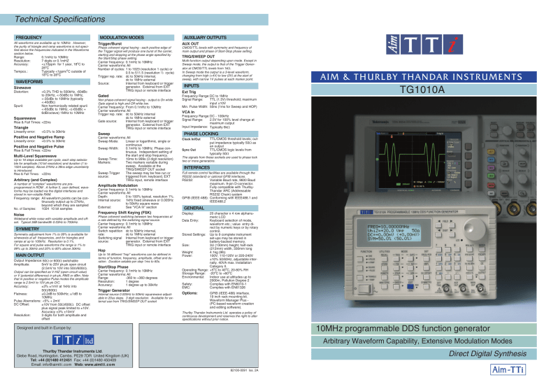
Technical Specifications FREQUENCY All waveforms are available up to 10MHz. However, the purity of triangle and ramp waveforms is not specified above the frequencies indicated in the Waveforms section below. Range: 0.1mHz to 10MHz Resolution: 7 digits or 0.1mHZ Accuracy: <±10ppm for 1 year, 18oC to 28oC Tempco.: Typically <1ppm/oC outside of 18oC to 28oC WAVEFORMS Sinewave Distortion: Spurii: <0.3% THD to 500kHz, -60dBc to 20kHz, <-50dBc to 1MHz, <-35dBc to 10MHz (typically <-40dBc) Non harmonically related spurii <-65dBc to 1MHz, <(-65dBc + 6dB/octave) 1MHz to 10MHz Squarewave Rise & Fall Times: <22ns Triangle Linearity error: <0.5% to 30kHz Positive and Negative Ramp Linearity error: <0.5% to 30kHz Positive and Negative Pulse Rise & Fall Times: <22ns Multi-Level Squarewave Up to 16 steps available per cycle, each step selectable for amplitude (10 bit resolution) and duration (1 to 1024 samples). Above 27kHz a 36ns edge uncertainty is introduced. Rise & Fall Times: <22ns Arbitrary (and Complex) A number of “complex” waveforms are preprogrammed in ROM . A further 5, user defined, waveforms may be loaded via the digital interfaces and stored in non-volatile RAM. Frequency range: All waveform points can be continuously output up to 27kHz, beyond which they are sampled No. of Samples: 1024 10 bit samples Noise Wideband white noise with variable amplitude and offset. Typical 3dB bandwidth 0.03Hz to 700kHz. SYMMETRY Symmetry adjustment from 1% to 99% is available for sinewaves at all frequencies, and for triangles and ramps at up to 100kHz. Resolution is 0.1%. For square and pulse waveforms the range is 1% to 99% up to 30kHz and 20% to 80% above 30kHz. MAIN OUTPUT Output Impedance: 50W or 600W switchable Amplitude: 5mV to 20V pk-pk open circuit (2.5mV to 10V into 50W/600W). Output can be specified as V-HiZ (open circuit value) or V (potential difference) in pk-pk, RMS or dBm. Note that in positive or negative Pulse modes the amplitude range is 2.5mV to 10V pk-pk O/C. Accuracy: ±3% ±1mV at 1kHz into 50W/600W Flatness: ±0.2dB to 500kHz; ±1dB to 10MHz Pulse Aberrations: <5% + 2mV DC Offset: ±10V from 50W/600W. DC offset plus signal peak limited to ±10V. Accuracy ±3% ±10mV Resolution: 3 digits for both amplitude and offset MODULATION MODES AUXILIARY OUTPUTS Trigger/Burst AUX OUT Phase coherent signal keying - each positive edge of the Trigger signal will produce one burst of the carrier, starting and stopping at the phase angle specified by the Start/Stop phase setting. Carrier frequency: 0.1mHz to 10MHz Carrier waveforms: All Number of cycles: 1 to 1023 (resolution 1 cycle) or 0.5 to 511.5 (resolution ½ cycle) Trigger rep. rate: dc to 50kHz internal, dc to 1MHz external Source: Internal from keyboard or trigger generator. External from EXT TRIG input or remote interface CMOS/TTL levels with symmetry and frequency of main output and phase of Start-Stop phase setting. Gated Non phase-coherent signal keying - output is On while Gate signal is high and Off while low. Carrier frequency: From 0.1mHz to 10MHz Carrier waveforms: All Trigger rep. rate: dc to 50kHz internal dc to 1MHz external Gate source: Internal from keyboard or trigger generator. External from EXT TRIG input or remote interface Sweep Carrier waveforms: All Sweep Mode: Linear or logarithmic, single or continuous Sweep Width: 0.1mHz to 10MHz. Phase continuous. Independent setting of the start and stop frequency. Sweep Time: 10ms to 999s (3 digit resolution) Markers: Two markers variable during sweep. Available at the TRIG/SWEEP OUT socket Sweep Trigger The sweep may be free run or source: triggered from: keyboard, EXT TRIG input, remote interface Amplitude Modulation Carrier frequency: 0.1mHz to 10MHz Carrier waveforms: All Depth: 0 to 100% typical, resolution 1%. Internal source: 1kHz fixed sinewave or 0.005Hz to 50kHz square wave External: See “VCA In” section Frequency Shift Keying (FSK) Phase coherent switching between two frequencies at a rate defined by the switching signal source. Carrier frequency: 0.1mHz to 10MHz Carrier waveforms: All Switch repetition dc to 50kHz internal, rate: dc to 1MHz external Switching signal Internal from keyboard or trigger source: generator. External from EXT TRIG input or remote interface Hop Up to 16 different “hop” waveforms can be defined in terms of function, frequency, amplitude, offset and duration. Duration setable per step 1ms to 60s. Start/Stop Phase Carrier frequency: 0.1mHz to 10MHz Carrier waveforms: All Range: -360 to +360 degrees Resolution: 1 degree Accuracy: 1 degree up to 30kHz Trigger Generator Internal source 0.005Hz to 50kHz squarewave adjustable in 20us steps. 3 digit resolution. Available for external use from TRIG/SWEEP OUT socket TRIG/SWEEP OUT Multi-function output depending upon mode. Except in Sweep mode, the output is that of the Trigger Generator at CMOS/TTL levels from 1kW. In Sweep mode the output is a 3-level waveform, changing from high (+4V) to low (0V) at the start of sweep, with narrow 1V pulses at each marker point. INPUTS Ext Trig Frequency Range:DC to 1MHz Signal Range: TTL (1.5V) threshold; maximum input ±10V Min. Pulse Width: 50ns (1ms for Sweep and HOP) AIM & TH UR L BY TH AND AR I N S T RU M E N T S TG1010A VCA In Frequency Range:DC - 100kHz Signal Range: 2.5V for 100% level change at maximum output Input Impedance: Typically 6kW PHASE LOCKING TTL/CMOS threshold levels; output impedance typically 50W as an output TTL/CMOS logic levels from Sync Out typically 50W The signals from these sockets are used to phase lock two or more generators. Clock In/Out INTERFACES Full remote control facilities are available through the RS232 (standard) or optional GPIB interfaces. RS232: Variable Baud rate, 9600 Baud maximum. 9-pin D-connector. Fully compatible with ThurlbyThandar ARC (Addressable RS232 Chain) system GPIB (IEEE-488): Conforming with IEEE488.1 and IEEE488.2 GENERAL Display: 20 character x 4 row alphanumeric LCD Data Entry: Keyboard selection of mode, waveform etc.; value entry direct by numeric keys or by rotary control. Stored Settings: Up to 9 complete instrument set-ups may be stored in battery-backed memory. Size: 3U (130mm) height; half-rack (212mm) width, 330mm long Weight: 4.1kg (9lb) Power: 100V, 110-120V or 220-240V ±10% 50/60Hz, adjustable internally. 40VA max. Installation Category II. Operating Range: +5oC to 40oC, 20-80% RH Storage Range: -20oC to +60oC Environmental: Indoor use at altitudes up to 2000m, Pollution Degree 2 Safety: Complies with EN6010-1 EMC: Complies with EN61326 Options: GPIB (IEEE-488) interface. 19 inch rack mounting kit. Waveform Manager Plus (PC-based waveform creation and editing software). Thurlby Thandar Instruments Ltd. operates a policy of continuous development and reserves the right to alter specifications without prior notice. 10MHz programmable DDS function generator Designed and built in Europe by: Arbitrary Waveform Capability, Extensive Modulation Modes Thurlby Thandar Instruments Ltd. Glebe Road, Huntingdon. Cambs. PE29 7DR United Kingdom (UK) Tel: +44 (0)1480 412451 Fax: +44 (0)1480 450409 Email: info@aimtti.com Web: www.aimtti.com Direct Digital Synthesis 82100-0091 Iss. 2A All the versatility of a function generator with the precision of Direct Digital Synthesis Powerfull modulation facilities Arbitrary waveform capability A DDS generator at a non-DDS price Powerful modulation modes Trigger/Burst Sweep AM The TG1010A breaks new ground by offering a DDS function generator at a similar price to that of a conventional generator of comparable functionality. It can generate a wide variety of waveforms between 0.1mHz and 10MHz with a resolution of 7 digits and an accuracy better than 10ppm. All waveforms can be swept over their full frequency range at a rate variable between 10 milliseconds and 15 minutes. The sweep is fully phase continuous. Sweep can be linear or logarithmic, single or continuous. Single sweeps can be triggered from the front panel, the trigger input, or the digital interfaces. Two sweep markers are provided which are adjustable whilst sweep is running. The markers can provide a visual indication of frequency points on a ‘scope or chart recorder. Amplitude Modulation is available for all waveforms and is variable in 1% steps up to 100%. An internal AM source is incorporated. Alternatively modulation can be controlled from an external generator. Direct digital synthesis for accuracy & stability Direct digital synthesis (DDS) is a technique for generating waveforms digitally using a phase accumulator, a look-up table and a DAC. The accuracy and stability of the resulting waveforms is related to that of the crystal master clock. The DDS generator offers not only exceptional accuracy and stability but also high spectral purity, low phase noise and excellent frequency agility. FSK Frequency Shift Keying provides phase coherent switching between two selected frequencies at a rate defined by the switching signal source. The rate can be set from dc to 50kHz internally, or dc to 1MHz externally. Phase continuous frequency sweep. All parameters can be entered directly from the numeric keypad. Alternatively most parameters can be incremented or decremented using the rotary encoder. Gated The Gated mode turns the output signal On when the gating signal is high and Off when it is low. Both Triggered and Gated modes can be operated from the internal Trigger Generator (0.005Hz to 50kHz) or from an external source (dc to 1MHz). The TG1010A generates high quality sine, square and pulse waveforms over the full frequency range of 0.1mHz to 10MHz. Triangle waveforms, ramp waveforms and multi-level squarewaves can also be generated subject to some limitations in the maximum useable frequencies. Variable symmetry/duty-cycle is available for all waveforms. Waveform hop Fully bus programmable The TG1010A has an RS-232 interface as standard which can be used for remote control of all of the instrument functions or for the down-loading of arbitrary waveforms. As well as operating as a conventional RS-232 interface, it can also be used in addressable mode whereby up to 32 instruments can be linked to one PC serial port as part of a TTi “ARC” system. Alternatively, a GPIB interface conforming to IEEE-488.2 is available as an option. The TG1010A is particularly easy to use. All of the main information is clearly displayed on a backlit LCD with 4 rows of 20 characters. Sub menus are used for the modulation modes and other complex functions. Single cycle burst, start-stop phase = 0o A wide range of waveforms Addressable RS-232 standard, GPIB optional All waveforms are available as a triggered burst whereby each positive edge of the Trigger signal will produce one burst of the carrier, starting and stopping at the phase angle specified by the start-stop phase setting. The number of cycles in the burst can be set between 0.5 and 1023. Easy and convenient to use u u u u u u u 0.1mHz to 10MHz frequency range, 7 digit resolution. Eight standard waveforms, plus multiple “complex” waveforms, true arbitrary waveforms and noise. Powerful modulation modes including Sweep, AM, Gating, Trigger/Burst, FSK and Hop. Variable symmetry, variable start/stop phase. 20V pk-pk output from 50 W or 600 W (switchable). Storage for five Arbitrary waveforms (1024 x 10-bits). Fully programmable via RS-232 or GPIB interfaces. The generator can be set up to ‘hop’ between a number of different waveform set-ups either at a pre-determined rate or in response to a manual or bus trigger. Up to 16 different hop waveforms can be defined in terms of frequency, amplitude, function, offset and duration, which is variable in 1ms steps up to 60 seconds. Noise generation The TG1010 can be set to simulate wide band random noise with adjustable amplitude and offset. Locked generators The signals from the Clock In/Out socket and the Sync Out socket can be used to phase lock two or more generators. This can be used to generate multi-phase waveforms or locked waveforms of different frequencies. Amplitude modulation using the internal sine wave modulation source. Pre-programmed ‘complex’ waveform. Arbitrary waveform capability Arbitrary waveforms can be loaded via the digital interfaces and then used in a similar way to the standard waveforms. Up to five arbitrary waveforms of 1024 10-bit words can be stored in non-volatile memory. The waveform clock is 27.48MHz maximum. This facility considerably expands the versatility of the TG1010A making it suitable for the generation of highly complex waveform patterns. In addition, the TG1010A offers numerous “complex” waveforms pre-defined in ROM. These include commonly used waveshapes such as sine x/x, decaying sinewave, exponential rise and fall etc. Optional software is available for the creation and editing of arbitrary waveforms on a personal computer. Frequency shifting on alternate cycles. Arbitrary waveform - simulated contact bounce. All the versatility of a function generator with the precision of Direct Digital Synthesis Powerfull modulation facilities Arbitrary waveform capability A DDS generator at a non-DDS price Powerful modulation modes Trigger/Burst Sweep AM The TG1010A breaks new ground by offering a DDS function generator at a similar price to that of a conventional generator of comparable functionality. It can generate a wide variety of waveforms between 0.1mHz and 10MHz with a resolution of 7 digits and an accuracy better than 10ppm. All waveforms can be swept over their full frequency range at a rate variable between 10 milliseconds and 15 minutes. The sweep is fully phase continuous. Sweep can be linear or logarithmic, single or continuous. Single sweeps can be triggered from the front panel, the trigger input, or the digital interfaces. Two sweep markers are provided which are adjustable whilst sweep is running. The markers can provide a visual indication of frequency points on a ‘scope or chart recorder. Amplitude Modulation is available for all waveforms and is variable in 1% steps up to 100%. An internal AM source is incorporated. Alternatively modulation can be controlled from an external generator. Direct digital synthesis for accuracy & stability Direct digital synthesis (DDS) is a technique for generating waveforms digitally using a phase accumulator, a look-up table and a DAC. The accuracy and stability of the resulting waveforms is related to that of the crystal master clock. The DDS generator offers not only exceptional accuracy and stability but also high spectral purity, low phase noise and excellent frequency agility. FSK Frequency Shift Keying provides phase coherent switching between two selected frequencies at a rate defined by the switching signal source. The rate can be set from dc to 50kHz internally, or dc to 1MHz externally. Phase continuous frequency sweep. All parameters can be entered directly from the numeric keypad. Alternatively most parameters can be incremented or decremented using the rotary encoder. Gated The Gated mode turns the output signal On when the gating signal is high and Off when it is low. Both Triggered and Gated modes can be operated from the internal Trigger Generator (0.005Hz to 50kHz) or from an external source (dc to 1MHz). The TG1010A generates high quality sine, square and pulse waveforms over the full frequency range of 0.1mHz to 10MHz. Triangle waveforms, ramp waveforms and multi-level squarewaves can also be generated subject to some limitations in the maximum useable frequencies. Variable symmetry/duty-cycle is available for all waveforms. Waveform hop Fully bus programmable The TG1010A has an RS-232 interface as standard which can be used for remote control of all of the instrument functions or for the down-loading of arbitrary waveforms. As well as operating as a conventional RS-232 interface, it can also be used in addressable mode whereby up to 32 instruments can be linked to one PC serial port as part of a TTi “ARC” system. Alternatively, a GPIB interface conforming to IEEE-488.2 is available as an option. The TG1010A is particularly easy to use. All of the main information is clearly displayed on a backlit LCD with 4 rows of 20 characters. Sub menus are used for the modulation modes and other complex functions. Single cycle burst, start-stop phase = 0o A wide range of waveforms Addressable RS-232 standard, GPIB optional All waveforms are available as a triggered burst whereby each positive edge of the Trigger signal will produce one burst of the carrier, starting and stopping at the phase angle specified by the start-stop phase setting. The number of cycles in the burst can be set between 0.5 and 1023. Easy and convenient to use u u u u u u u 0.1mHz to 10MHz frequency range, 7 digit resolution. Eight standard waveforms, plus multiple “complex” waveforms, true arbitrary waveforms and noise. Powerful modulation modes including Sweep, AM, Gating, Trigger/Burst, FSK and Hop. Variable symmetry, variable start/stop phase. 20V pk-pk output from 50 W or 600 W (switchable). Storage for five Arbitrary waveforms (1024 x 10-bits). Fully programmable via RS-232 or GPIB interfaces. The generator can be set up to ‘hop’ between a number of different waveform set-ups either at a pre-determined rate or in response to a manual or bus trigger. Up to 16 different hop waveforms can be defined in terms of frequency, amplitude, function, offset and duration, which is variable in 1ms steps up to 60 seconds. Noise generation The TG1010 can be set to simulate wide band random noise with adjustable amplitude and offset. Locked generators The signals from the Clock In/Out socket and the Sync Out socket can be used to phase lock two or more generators. This can be used to generate multi-phase waveforms or locked waveforms of different frequencies. Amplitude modulation using the internal sine wave modulation source. Pre-programmed ‘complex’ waveform. Arbitrary waveform capability Arbitrary waveforms can be loaded via the digital interfaces and then used in a similar way to the standard waveforms. Up to five arbitrary waveforms of 1024 10-bit words can be stored in non-volatile memory. The waveform clock is 27.48MHz maximum. This facility considerably expands the versatility of the TG1010A making it suitable for the generation of highly complex waveform patterns. In addition, the TG1010A offers numerous “complex” waveforms pre-defined in ROM. These include commonly used waveshapes such as sine x/x, decaying sinewave, exponential rise and fall etc. Optional software is available for the creation and editing of arbitrary waveforms on a personal computer. Frequency shifting on alternate cycles. Arbitrary waveform - simulated contact bounce. Technical Specifications FREQUENCY All waveforms are available up to 10MHz. However, the purity of triangle and ramp waveforms is not specified above the frequencies indicated in the Waveforms section below. Range: 0.1mHz to 10MHz Resolution: 7 digits or 0.1mHZ Accuracy: <±10ppm for 1 year, 18oC to 28oC Tempco.: Typically <1ppm/oC outside of 18oC to 28oC WAVEFORMS Sinewave Distortion: Spurii: <0.3% THD to 500kHz, -60dBc to 20kHz, <-50dBc to 1MHz, <-35dBc to 10MHz (typically <-40dBc) Non harmonically related spurii <-65dBc to 1MHz, <(-65dBc + 6dB/octave) 1MHz to 10MHz Squarewave Rise & Fall Times: <22ns Triangle Linearity error: <0.5% to 30kHz Positive and Negative Ramp Linearity error: <0.5% to 30kHz Positive and Negative Pulse Rise & Fall Times: <22ns Multi-Level Squarewave Up to 16 steps available per cycle, each step selectable for amplitude (10 bit resolution) and duration (1 to 1024 samples). Above 27kHz a 36ns edge uncertainty is introduced. Rise & Fall Times: <22ns Arbitrary (and Complex) A number of “complex” waveforms are preprogrammed in ROM . A further 5, user defined, waveforms may be loaded via the digital interfaces and stored in non-volatile RAM. Frequency range: All waveform points can be continuously output up to 27kHz, beyond which they are sampled No. of Samples: 1024 10 bit samples Noise Wideband white noise with variable amplitude and offset. Typical 3dB bandwidth 0.03Hz to 700kHz. SYMMETRY Symmetry adjustment from 1% to 99% is available for sinewaves at all frequencies, and for triangles and ramps at up to 100kHz. Resolution is 0.1%. For square and pulse waveforms the range is 1% to 99% up to 30kHz and 20% to 80% above 30kHz. MAIN OUTPUT Output Impedance: 50W or 600W switchable Amplitude: 5mV to 20V pk-pk open circuit (2.5mV to 10V into 50W/600W). Output can be specified as V-HiZ (open circuit value) or V (potential difference) in pk-pk, RMS or dBm. Note that in positive or negative Pulse modes the amplitude range is 2.5mV to 10V pk-pk O/C. Accuracy: ±3% ±1mV at 1kHz into 50W/600W Flatness: ±0.2dB to 500kHz; ±1dB to 10MHz Pulse Aberrations: <5% + 2mV DC Offset: ±10V from 50W/600W. DC offset plus signal peak limited to ±10V. Accuracy ±3% ±10mV Resolution: 3 digits for both amplitude and offset MODULATION MODES AUXILIARY OUTPUTS Trigger/Burst AUX OUT Phase coherent signal keying - each positive edge of the Trigger signal will produce one burst of the carrier, starting and stopping at the phase angle specified by the Start/Stop phase setting. Carrier frequency: 0.1mHz to 10MHz Carrier waveforms: All Number of cycles: 1 to 1023 (resolution 1 cycle) or 0.5 to 511.5 (resolution ½ cycle) Trigger rep. rate: dc to 50kHz internal, dc to 1MHz external Source: Internal from keyboard or trigger generator. External from EXT TRIG input or remote interface CMOS/TTL levels with symmetry and frequency of main output and phase of Start-Stop phase setting. Gated Non phase-coherent signal keying - output is On while Gate signal is high and Off while low. Carrier frequency: From 0.1mHz to 10MHz Carrier waveforms: All Trigger rep. rate: dc to 50kHz internal dc to 1MHz external Gate source: Internal from keyboard or trigger generator. External from EXT TRIG input or remote interface Sweep Carrier waveforms: All Sweep Mode: Linear or logarithmic, single or continuous Sweep Width: 0.1mHz to 10MHz. Phase continuous. Independent setting of the start and stop frequency. Sweep Time: 10ms to 999s (3 digit resolution) Markers: Two markers variable during sweep. Available at the TRIG/SWEEP OUT socket Sweep Trigger The sweep may be free run or source: triggered from: keyboard, EXT TRIG input, remote interface Amplitude Modulation Carrier frequency: 0.1mHz to 10MHz Carrier waveforms: All Depth: 0 to 100% typical, resolution 1%. Internal source: 1kHz fixed sinewave or 0.005Hz to 50kHz square wave External: See “VCA In” section Frequency Shift Keying (FSK) Phase coherent switching between two frequencies at a rate defined by the switching signal source. Carrier frequency: 0.1mHz to 10MHz Carrier waveforms: All Switch repetition dc to 50kHz internal, rate: dc to 1MHz external Switching signal Internal from keyboard or trigger source: generator. External from EXT TRIG input or remote interface Hop Up to 16 different “hop” waveforms can be defined in terms of function, frequency, amplitude, offset and duration. Duration setable per step 1ms to 60s. Start/Stop Phase Carrier frequency: 0.1mHz to 10MHz Carrier waveforms: All Range: -360 to +360 degrees Resolution: 1 degree Accuracy: 1 degree up to 30kHz Trigger Generator Internal source 0.005Hz to 50kHz squarewave adjustable in 20us steps. 3 digit resolution. Available for external use from TRIG/SWEEP OUT socket TRIG/SWEEP OUT Multi-function output depending upon mode. Except in Sweep mode, the output is that of the Trigger Generator at CMOS/TTL levels from 1kW. In Sweep mode the output is a 3-level waveform, changing from high (+4V) to low (0V) at the start of sweep, with narrow 1V pulses at each marker point. INPUTS Ext Trig Frequency Range:DC to 1MHz Signal Range: TTL (1.5V) threshold; maximum input ±10V Min. Pulse Width: 50ns (1ms for Sweep and HOP) AIM & TH UR L BY TH AND AR I N S T RU M E N T S TG1010A VCA In Frequency Range:DC - 100kHz Signal Range: 2.5V for 100% level change at maximum output Input Impedance: Typically 6kW PHASE LOCKING TTL/CMOS threshold levels; output impedance typically 50W as an output TTL/CMOS logic levels from Sync Out typically 50W The signals from these sockets are used to phase lock two or more generators. Clock In/Out INTERFACES Full remote control facilities are available through the RS232 (standard) or optional GPIB interfaces. RS232: Variable Baud rate, 9600 Baud maximum. 9-pin D-connector. Fully compatible with ThurlbyThandar ARC (Addressable RS232 Chain) system GPIB (IEEE-488): Conforming with IEEE488.1 and IEEE488.2 GENERAL Display: 20 character x 4 row alphanumeric LCD Data Entry: Keyboard selection of mode, waveform etc.; value entry direct by numeric keys or by rotary control. Stored Settings: Up to 9 complete instrument set-ups may be stored in battery-backed memory. Size: 3U (130mm) height; half-rack (212mm) width, 330mm long Weight: 4.1kg (9lb) Power: 100V, 110-120V or 220-240V ±10% 50/60Hz, adjustable internally. 40VA max. Installation Category II. Operating Range: +5oC to 40oC, 20-80% RH Storage Range: -20oC to +60oC Environmental: Indoor use at altitudes up to 2000m, Pollution Degree 2 Safety: Complies with EN6010-1 EMC: Complies with EN61326 Options: GPIB (IEEE-488) interface. 19 inch rack mounting kit. Waveform Manager Plus (PC-based waveform creation and editing software). Thurlby Thandar Instruments Ltd. operates a policy of continuous development and reserves the right to alter specifications without prior notice. 10MHz programmable DDS function generator Designed and built in Europe by: Arbitrary Waveform Capability, Extensive Modulation Modes Thurlby Thandar Instruments Ltd. Glebe Road, Huntingdon. Cambs. PE29 7DR United Kingdom (UK) Tel: +44 (0)1480 412451 Fax: +44 (0)1480 450409 Email: info@aimtti.com Web: www.aimtti.com Direct Digital Synthesis 82100-0091 Iss. 2A Product Summary Company name and product brands Laboratory Power Supplies Bench and system power supplies from 30 watts up to 1200 watts using linear, mixed-mode and PowerFlex regulation technologies. Thurlby Thandar Instruments Ltd. (TTi) is one of Europe’s leading manufacturers of test and measurement instruments. Waveform Generators Analog and digital (DDS) function generators, true arbitrary generators, arbitrary/function generators and pulse generators. In the future, however, the full product range will be branded Aim-TTi. Products have been sold under two brand names: TTi and Aim. This changeover will be gradual and many products will continue to carry the TTi or Aim brands for some time to come. Web Addresses (URLs) Precision Measurement Instruments Benchtop DMMs, frequency counters, component measurement instruments (LCR), electronic dc loads, current probes. The preferred URL for obtaining information concerning Aim-TTi products is: www.aimtti.com (international customers) Customers in the UK should use the URL: www.aimtti.co.uk RF and EMC Test Equipment Spectrum analyzers, signal generators, frequency counters, power meters, emc measurement instruments. Customers in the USA should use the URL: www.aimtti.us Note that previous URLs such as www.tti-test.com will continue to operate for the time being. Designed and built in Europe by: Thurlby Thandar Instruments Ltd. Glebe Road, Huntingdon, Cambridgeshire PE29 7DR England (United Kingdom) Tel: +44 (0)1480 412451 Fax: +44 (0)1480 450409 Email: info@aimtti.com Web: www.aimtti.com
